Table of Contents
Advertisement
Quick Links
Kurzanleitung / Brief Instruction
Handansteuereinrichtung HE 083
Emergency Override Switch HE 083
HE 083 — SP-300/SP-600
KA_HE-083_10
1. Allgemein / In general
1.
1.1 Bestimmungsgemäßer Gebrauch
Die elektrische Handansteuereinrichtung wird in Rauch- und
Wärmeableitungsanlagen des Typs SP-300/SP-600 einge-
setzt. Sie dient dazu, im Brandfall die jeweilige elektrische
Steuereinrichtung per Handauslösung anzusteuern und somit
den Rauchabzug zu aktivieren. Zudem erfolgt eine Visualisie-
rung von Betriebszuständen der Steuereinrichtung.
1.1 Use for the intended purpose
The electric emergency switch is used in SHE-Systems. In the
case of fire it can be used to activate the electrical control sys-
tem and start the smoke funnel by hand. It shows additionally
the condition of the control system.
1.2 Funktionsbeschreibung / Functional description
1.2.1 Verwendete Symbole / Symbols
LED Anzeige rot
(Dauerlicht)
LED-sign red
(permanent light)
LED Anzeige grün
(Dauerlicht)
LED-sign green
(permanent light)
LED Anzeige gelb
(Blinkfunktion)
LED-sign yellow
(blink light)
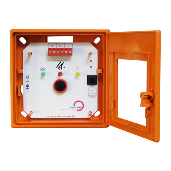
1.3 Handansteuereinrichtung HE 083
Komponenten der Hauptbedienstelle:
• Stoßfestes Kunststoffgehäuse nach prEN 12101-9 /
DIN EN 54-11 und VdS 2592 mit Drehtüre.
• Brechbares Element (Einschlagscheibe)
• Schlüssel
• Platine bestückt mit:
LED-Anzeige „grün" für Betriebszustand OK
LED-Anzeige „gelb" für Sammelstörung
LED-Anzeige „rot" für Betriebszustand ALARM
Druck-Taster ALARM
Druck-Taster RESET (Alarm Rückstellung)
KA_HE-083_10
Ausgabe/Issue: 1.0/11.2014
HE 083 — SP-300/SP-600
RWA-Alarm Auslösung
SHE-alarm activation
Betriebsbereit (OK)
ready for operation (OK)
Sammelstörung
failure
www.simon-rwa.de
info@simon-rwa.de
Abbildung exemplarisch! / exemplary picture!
1.3 Emergency override switch HE 083
Parts of the main station:
• Plastic housing (surface) according to DIN 14655 /
EN 12101/9 and VdS 2592 with side hinged door.
• Breaking element (break glass plane)
• Key
• Circuit board assembled with:
LED-sign "green" for operating condition OK
LED-sign "yellow" for failure
LED-sign "red" for operating condition ALARM
Push-button ALARM
Push-button RESET (Alarm reset)
1.4 Technische Daten / Technical data
Tabelle 1: Elektrische Eigenschaften
Tabular 1: Electrical characteristics
Maximale Anzahl Handansteuereinrichtun-
gen (HE 083) pro SP-300/-600:
Maximum number of emergency switch
(HE 083) per SP-300/-600:
Ausgangsspannungsbereich
(B1):
Output voltage range (B1):
Strombelastbarkeit (B1):
Current carrying capacity
(B1):
Stromüberwachungsfenster
(OK-Bereich):
Monitoring current
(OK-range):
2
Klemme
17,5 V DC bis
1 und 2
18 V DC
Clamp
17.5 V DC to
1 and 2
18 V DC
Klemme
1 und 2
max. 120 mA
Clamp
1 and 2
Klemme
1 und 2
100 μA bis / to 5 mA
Clamp
1 and 2
Datum/Date: 2014-11-10
Seite/Page 1/3
Advertisement
Table of Contents

Summary of Contents for SIMON RWA HE 083
- Page 1 It shows additionally the condition of the control system. Abbildung exemplarisch! / exemplary picture! 1.2 Funktionsbeschreibung / Functional description 1.3 Emergency override switch HE 083 1.2.1 Verwendete Symbole / Symbols Parts of the main station: LED Anzeige rot RWA-Alarm Auslösung...
- Page 2 Bei Verwendung von zwei HE 083 in Reihe ist der 27 kΩ Wider- stand beim leitungsmäßig letzten HE 083 zur Schleifenverbindung einzusetzen. For use of more than one emergency switch HE 083 in a row the 27 kΩ resistor for monitoring must be placed in the last switch. www.simon-rwa.de...
- Page 3 Kurzanleitung / Brief Instruction Handansteuereinrichtung HE 083 Emergency Override Switch HE 083 Pflege und Wartung / Care and maintenance 3. Pflege und Wartung / Care and maintenance Der Wartungsablauf erfolgt nach einer vom Hersteller zu bezie- henden Checkliste. The maintenance sequence carried out after a Checklist to be purchased from the manufacturer.
Need help?
Do you have a question about the HE 083 and is the answer not in the manual?
Questions and answers