Advertisement
Quick Links
Advertisement

Related Manuals for Mach Power NW-SP4-001


Summary of Contents for Mach Power NW-SP4-001
- Page 1 INSTALLATION GUIDE...
- Page 3 Thanks for choosing Mach Power products...
-
Page 5: Table Of Contents
Contents POE Products Introduction Product Features Panel Layout Installation Instruction Operation Cautions Desktop Mounting Rack Mounting Making power connection... -
Page 6: Poe Products Introduction
Please read this user’s guide carefully before operating. 1.1 POE Products Introduction 1 POE Switches Total Model Number Total Ports POE Standards Power/port ports power 4x10/100M PoE NW-SP4-001 IEEE 802.3af/at 15.4W/30W 45/65W 1x10/100M 4x10/100M PoE SW-UF4L4P-014 IEEE 802.3af/at 15.4W/30W 4x10/100M NW-SP8-002 8x10/100M PoE IEEE 802.3af/at... -
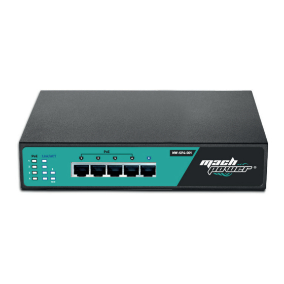
Page 7: Panel Layout
1.2 Panel Layout NW-SP4-001 4x10/100M PoE ports +1x10/100M ports, Total power:45W/65W Led indicator Description Led States Function The switch is powered on. Power The switch is powered off. POE power supply works. No POE power supply. POE power The POE port is failed or PD connection... - Page 8 SW-UF4L4P-014 4x10/100M PoE ports + 4x10/100M ports LED Indicator is the same with NW-SP4-001 (above) NW-SP8-002 8x10/100M PoE ports LED Indicator is the same with NW-SP4-001 (above) SW-UG4L4P-001 4x10/100/1000M PoE ports + 4x10/100/1000M ports...
- Page 9 Led indicator Description State Function The switch is powered on. Power Green The switch is powered off. The system is starting. System Green Blinking The system works normally. POE power supply works. No POE power supply. POE power The POE port is failed or PD connection is Blinking overloaded, please remove PDs and recon- nect after checking.
-
Page 10: Installation Instruction
Installation Instruction Please open the product packaging box with care and check the following items shipped with product: 2.1 Operation Cautions 1. Don’t stock the device in damp environment or near water, to avoid water or moisture pene- trating into the inner device. 2. -
Page 11: Making Power Connection
2.2 Making power connection POE switches and POE Injectors is designed for AC 90~264V/50~60Hz Power Supply. We advise to adopt a one-phase 3-wire power socket with neutral point joint or multifunctional computer pow- er socket. Please make sure there are no problems on power supply, connection and grounding before you start operating the POE devices, or the devices will get damaged.
Need help?
Do you have a question about the NW-SP4-001 and is the answer not in the manual?
Questions and answers