Table of Contents
Advertisement
Quick Links
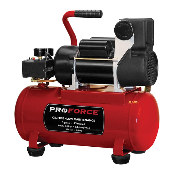
Operator-Parts Manual
Oilless, Single Stage, Direct Drive, Electric Air Compressors
Product style and configuration may
vary.
Specification Chart
RUNNING
MODEL NO.
H.P.
(CV)
VPF1080318
1.0
WARNING: Read and understand all safety precautions in this manual before operating. Failure to comply with
instructions in this manual could result in personal injury, property damage, and/or voiding of your warranty. The
manufacturer WILL NOT be liable for any damage because of failure to follow these instructions.
?
Questions? See back page.
VOLTAGE/AMPS/
TANK CAPACITY
GALLONS
3 (11,4)
KICK-IN
PRESSURE
PHASE
95
120/12/1
(6,55 bar)
200-2705 (E103525)_ Rev A_7-08
200-2705
E103525
Revision A
KICK-OUT
PRESSURE
125
(8,62 bar)
Advertisement
Table of Contents

Summary of Contents for Pro Force VPF1080318
- Page 1 PRESSURE PRESSURE PHASE GALLONS H.P. (CV) VPF1080318 3 (11,4) 120/12/1 (6,55 bar) (8,62 bar) WARNING: Read and understand all safety precautions in this manual before operating. Failure to comply with instructions in this manual could result in personal injury, property damage, and/or voiding of your warranty. The manufacturer WILL NOT be liable for any damage because of failure to follow these instructions.
-
Page 2: Table Of Contents
TABLE OF CONTENTS SAFETY GUIDELINES ......3 Checking the Relief Valve ....16 OVERVIEW . -
Page 3: Safety Guidelines
SAFETY GUIDELINES The following information relates to protecting YOUR SAFETY and PREVENTING EQUIPMENT PROBLEMS. To help you recognize this information, we use the following symbols. Please read the manual and pay attention to these sections. – A POTENTIAL HAZARD THAT WILL CAUSE SERIOUS INJURY OR LOSS OF LIFE. DANGER: –... -
Page 4: Overview
OVERVIEW BASIC AIR COMPRESSOR COMPONENTS Oilless air compressors are factory lubricated for life and do not require any oil. The basic components of the air compressor are the electric motor, pump, pressure switch, and tank. The electric motor (see A) powers the pump. The electric motor is equipped with an overload protector and an automatic reset. -
Page 5: Assembly
ASSEMBLY ASSEMBLING THE COMPRESSOR Unpack the air compressor. Inspect the unit for damage. If the unit has been damaged in transit, contact the carrier and complete a damage claim. Do this immediately because there are time limitations to damage claims. Check the compressor’s serial label to ensure that you have received the model ordered, and that it has the required pressure rating for its intended use. -
Page 6: Compressor Controls
COMPRESSOR CONTROLS COMPRESSOR CONTROLS ON/OFF Switch (see A) This switch turns on the compressor. It is operated manually, but when in the ON position, it allows the compressor to start up or shut down automatically, without warning, upon air demand. ALWAYS set this switch to OFF when the compressor is not being used, and before unplugging the compressor. -
Page 7: Electrical Power Requirements
ELECTRICAL POWER REQUIREMENTS ELECTRICAL WIRING Figure 1 Refer to the air compressor’s serial label for the unit’s voltage and amperage requirements. Grounded Outlet Box EXTENSION CORDS NOTE: Avoid use of extension cords. For optimum performance, plug the compressor power cord directly into a grounded wall socket. Do not use an Grounded Outlet extension cord unless absolutely necessary. -
Page 8: Operating Instructions
OPERATING INSTRUCTIONS DAILY STARTUP Turn the ON/OFF switch to the OFF position (see A). Close the tank drain valve (see D). Turn in the clockwise direction. Plug in the power cord. WARNING: High temperatures are generated by the electric motor and the pump. To prevent burns or other injuries, DO NOT touch the compressor while it is running. -
Page 9: Maintenance
MAINTENANCE MAINTENANCE WARNING: To avoid personal injury, always shut off and unplug the compressor and relieve all air pressure from the system before performing any service on the air compressor. Regular maintenance will ensure trouble free operation. Your electric powered air compressor represents high quality engineering and construction;... - Page 10 PARTS LIST ITEM # 59 040-0418 (U2C) Pump Breakdown ITEM # 60 ITEM # 61 200-2705...
- Page 11 PARTS LIST Qty Description Item Part No Order item #59 Air Filter, Cap Order item #59 Air Filter, Element Order item #59 Air Filter, Base 040-0418 Motor/Pump Asm 145-0585 Tube, Relief Nut, Comp, 1/4" Ferrule, 1/4" Power Cord Strain Relief 136-0098 Safety Valve 034-0224...
-
Page 12: Checking The Relief Valve
MAINTENANCE CHECKING THE RELIEF VALVE Pull the relief valve daily to ensure that it is operating properly and to clear the valve of any possible obstructions. TESTING FOR LEAKS Check that all connections are tight. A small leak in any of the hoses, transfer tubes, or pipe connections will substantially reduce the performance of your air compressor. -
Page 13: Troubleshooting Chart
TROUBLESHOOTING CHART Note: Troubleshooting problems may have similar causes and solutions. PROBLEM POSSIBLE CAUSE SOLUTION Tank drain valve is open Close drain valve Low pressure or not enough air Check fittings with soapy water. Tighten or reseal leaking fittings. Fittings Leak DO NOT OVERTIGHTEN. - Page 14 PARTS AND SERVICE Replacement parts and service are available from your When needing service, please contact the nearest nearest authorized Service Center. If the need arises, authorized Service Center or call: contact Product Service as listed at right. PRODUCT SERVICE When consulting with a Service Center or Product Service, refer to the model number and serial number located on the serial label of the compressor.
Need help?
Do you have a question about the VPF1080318 and is the answer not in the manual?
Questions and answers