Table of Contents
Advertisement
Quick Links
Ropax
™
JUMBO MOBILE COMPACTOR
Original operating manual
Machine type
RPM 7700 - VII
Serial no.
Year of manufacture
Operating manual no.
174 18
14641 Arminta Street • Panorama City, CA 91402 • Toll Free: 800.220.6776
Telephone: 818.994.2870 • Fax: 818.994.4032 • info@Epaxsystems.com • www.Epaxsystems.com
Advertisement
Table of Contents

Subscribe to Our Youtube Channel
Summary of Contents for EPAX ROPAX RPM 7700 VII
- Page 1 Ropax ™ JUMBO MOBILE COMPACTOR Original operating manual Machine type RPM 7700 - VII Serial no. Year of manufacture Operating manual no. 174 18 14641 Arminta Street • Panorama City, CA 91402 • Toll Free: 800.220.6776 Telephone: 818.994.2870 • Fax: 818.994.4032 • info@Epaxsystems.com • www.Epaxsystems.com...
- Page 2 Marketed by Epax in North America as ROPAX ROLLING COMPACTORS. EPAX Systems, Inc., 14641 Arminta Street • Panorama City, CA 91402 • Toll Free: 800.220.6776 Telephone: 818.994.2870 • Fax: 818.994.4032 • info@epaxsystems.com • www.epaxsystems.com...
-
Page 3: Table Of Contents
Table of contents Intended use ........................1.01 Preface ........................ 1.01 Basic information ....................1.02 Information on this operating manual ..............1.02 Intended use ....................... 1.03 Introduction ........................2.01 Machine overview ....................2.01 Operating keyboard overview ................2.02 Joystick overview ....................2.03 Function description .................... - Page 4 Table of contents The driving mode ....................5.03 Measures to take if the Jumbo Mobile Compactor tips over ....... 5.05 Precautionary measures in different weather situations ........5.05 5.4.1 At high outdoor temperatures ..............5.05 5.4.2 At low outdoor temperatures ..............5.06 The compaction mode ..................
- Page 5 Table of contents 12. Towing and transport ..................... 12.01 12.1 Towing ......................... 12.01 12.2 Short-circuiting the travel drive ................12.01 12.3 The transport ....................... 12.02 12.4 Loading the Jumbo Mobile Compactor onto a transport vehicle ......12.02 12.5 Loading by crane ....................12.02 12.6 Independent driving onto a transport device ............
- Page 6 Ensure that the operating manual is always in the Epax Systems Jumbo Mobile Compactor. The operating manual must be read and used by all persons working with or on the Epax Systems Jumbo Mobile Compactor, e.g. in the context of:...
- Page 7 Basic information It is not permitted to use the Epax Systems Jumbo Mobile Compactor on public roads. As its maximum speed is 6 km/h, it does not require registration. Each new user must receive instruction prior to using the vehicle for the first time.
-
Page 8: Intended Use
This machine is a mobile waste compactor only designed for compacting materials and waste in open containers and therefore only intended for this purpose. Any other or further use is regarded as use other than that intended. Epax Systems does not assume any liability for damage resulting from the above. The intended use also includes •... -
Page 9: Machine Overview
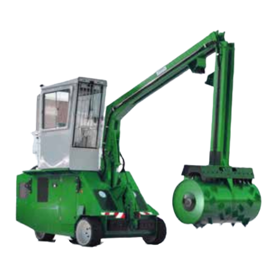
Machine overview Pendulum arm Driver’s cab with control panel Compaction roller Cranked arm Container Engine bonnet Connection hook for container Maintenance doors (additional option) Diesel engine Hazard area Diesel tank Hydraulic unit All figures, drawings, etc. are based on standard versions and may deviate. -
Page 10: Operating Keyboard Overview
Operating keyboard overview Malfunction Display, engine 15 Release for roller operation Travel path adjustment Fuel display 16 Front light Grease container empty EMERGENCY STOP 17 Rear light Windscreen wiper water Multi-function display for driving mode 18 Joystick Mains operation START 19 Horn Spare Ignition lock... -
Page 11: Joystick Overview
Joystick overview Sliding switch Driving mode Roller mode green and yellow button Sliding switch in mid-position: - 0 position - automatic parking brake active Sliding switch in front position: - driving mode active - automatic parking brake deactivated - lifting/lowering container hook active (up: green button; down: yellow button) Sliding switch in back position: - roller mode active - automatic parking brake active... -
Page 12: Function Description
As you probably know from your own experience, great volumes of waste and refuse are still disposed of in open containers. Loose collection leads to low effective volumes and frequent transport for disposal. Your container fills up quickly, waste materials roll around in the container and the cost of waste disposal is high. The Epax Systems Jumbo Mobile Compactor, which is placed next to open containers as an additional unit, provides significant advantages for waste disposal. It will help you reduce the number of disposal transport runs to an efficient minimum, while allowing you to keep your old waste disposal system. -
Page 13: Technical Data
Adjustment is automatic and infinitely variable, but load-dependent. The travel speed is based on the unit’s load. The joystick is used to start driving. The variable pump is controlled based on the speed of the Epax Systems Jumbo Mobile Compactor. The higher the load on the Epax Systems Jumbo Mobile Compactor, the lower the ideal utilization of the overall capacity. The joystick can also be used to affect the control in such a way that the Epax Systems Jumbo Mobile Compactor is slowed down to a halt. - Page 14 The steering and operating hydraulics are supplied with oil by a triple hydraulic gear pump. The gear pump is connected to the variable pump of the travel drive. The hydraulic system is equipped with pressure limitation valves, filters and an oil cooler. Electrical system The electrical system has an operating voltage of 12 Volt. The consumers and their supply lines are equipped with fuses.
-
Page 15: Checks Prior To Start
Control and warning lights Danger of accidents due to malfunction! If a red control light lights up while the engine is running, immediately shut down the engine. Remedy the error (see chapter 13). Do not continue working with the Jumbo Mobile Compactor until the error has been remedied. - Page 16 Service The ROPAX™ JUMBO ROLLING COMPACTOR is designed to give you reliable service and superior performance for many years. To realize the best performance and the safest operation of your ROPAX™ Jumbo Rolling Compactor, everyone involved in its operation and service should read and thoroughly understand the contents of this manual and follow all of its instructions and warnings.
- Page 17 Lock-Out and Tag-Out Instructions FOREWORD: Before entering any part of the compactor, be sure that all sources of energy have been shut off, all potential hazards have been eliminated, and the compactor is locked-out and tagged-out in accordance with OSHA and ANSI requirements. The specific lock-out and tag-out instructions may vary from company to company (i.e. multiple locks may be required, or other machinery may need to be locked out and tagged-out).
-
Page 18: Explanation Of Symbols And Notes
Explanation of symbols and notes The following symbols are used for danger in the operating manual and on the machine: This symbol signals a potential danger for life and health of persons. Non-adherence to this information can result in injuries or even death. This symbol signals a potentially dangerous situation. -
Page 19: Basic Safety Rules
This symbol indicates that the operating personnel must wear hearing protection. This symbol warns against opening and removing protective devices/ guards while the engine is running. Basic safety rules The safety and availability of the machine depends on adherence to these regulations. -
Page 20: Safety And Protective Devices
The machine may only be moved on paved surfaces such as blacktop, pavement, etc. The maximum permissible incline is 11% (6.5°). If the machine is operated with the container moving unit as additional equipment, the max. incline while a container is hooked in is 2%. In addition to the operating manual, always adhere to the general and local regulations regarding accident prevention and environmental protection. - Page 21 Do not take any measures that may impact safety. Prior to starting work, familiarize yourself with the work conditions at the site. The working site includes e.g. obstacles within the operating and driving range, the load bearing capacity of the ground and necessary measures for cordoning off the site from public traffic.
- Page 22 3.2.3 Danger caused by electrical energy Adhere to these 5 safety rules for work on the machine: - disconnect, - secure against restarting, - ascertain that the machine is voltage-free, - ground and short-circuit, - cover or fence off nearby live components. Have all work on the electric supply carried out by a qualified electrician.
-
Page 23: Depressurizing The Machine
3.2.6 Hazards caused by misuse Do not drive the Jumbo Mobile Compactor up inclines of over 11% (6.5°) or 2% for machines with a container moving unit. Epax Systems cannot guarantee the Jumbo Mobile Compactor’s stability for inclines of over 11 respectively 2%. -
Page 24: Safety And Precautionary Measures In Public Areas
Only use original spare parts for replacement. After completing the maintenance work, check all safety devices/guards for proper function (see chapter 3.2.10), and reinstall all covers, cleaning flaps, etc., then ensure that they are tightly fitted. Switch of the machine and secure it against being switched on again. Also use wedges to secure the machine against rolling away. If service work can only be carried out with the operating equipment raised, place a suitable support underneath the equipment for safety! When changing wheels, place the machine on level, straight, paved ground and use wedges to... -
Page 25: The Safety Devices/Guards
3.2.10 The safety devices/guards Always check the following safety devices for proper function before starting up the machine. The main switch If the main switch is pushed down, the machine is switched off on all poles. ON It is not possible to switch on the machine (see also chapter 4.3.2). The EMERGENCY STOP button If the EMERGENCY STOP buttons is pressed, the machine is stopped. -
Page 26: The Assembly
4.1 The assembly The Jumbo Mobile Compactor must be unloaded, set up, assembled and instructions must be given by trained personnel authorized by Epax Systems. 4.2 The disassembly The Jumbo Mobile Compactor must be dismantled, packaged and loaded by trained personnel authorized by Epax Systems. -
Page 27: Checks Prior To Entering
4.3.1 Checks prior to entering Check for cleanliness and damage. Ensure that handles and foot boards are in perfect condition and clean. Check that the cab is undamaged and clean. Check that all screws, joints and pivot pins as well as the coolers are clean. Check all screws, joints and pivot pins for tightness. -
Page 28: Adjusting The Driver's Seat
4.3.3 Adjusting the driver’s seat Danger of accidents due to distraction! Do not adjust the driver’s seat while driving, but only while the Jumbo Mobile Compactor is not moving! You can adjust the driver’s seat to your size and posture as required. This prevents muscle tension and fatigue during work. -
Page 29: Adjusting The Steering Column
4.3.4 Adjusting the steering column Danger of accidents due to distraction! Do not adjust the steering column while driving, but only while the Jumbo Mobile Compactor is not moving! You can adjust the position of the steering column lengthwise to adapt it to your individual requirements for size and posture. -
Page 30: The Travel Path Adjustment
The travel path adjustment 1) Release the EMERGENCY STOP button by turning it clockwise. Sliding switch 2) Start the diesel engine as described in Driving mode section 5.1. 3) Push forward the sliding switch on the joystick (automatic parking brake is deactivated, driving mode is active). - Page 31 To set the front reversal position push the joystick forward until the desired reversal position is reached. Return the joystick to its center position, then press the yellow ore green button (roller stops). Press the travel length setting button to Front Rear position...
-
Page 32: Starting Up The Diesel Engine
Starting up the diesel engine 5.1.1 Daily checks To prevent malfunctions, ensure that the engine is kept in the best possible operating condition. For this reason, check the items listed below every day. For further information and instructions, refer to the operating manual of the diesel engine. -
Page 33: Start-Up
5.1.2 Start-up Turn the ignition key (1) clockwise. The display (2) is activated and “pre-igniting” is displayed. Press the START button (3). This starts the engine. If the engine does not start, attempt the starting process again after a brief break. Attention! If the engine cannot be started, please check the oil level! If the ambient... - Page 34 5.2 The driving mode Ensure that nobody is in the hazard area while driving the Jumbo Mobile The compaction roller must be completely raised during driving mode. The Jumbo Mobile Compactor may only be operated on firm, level ground. The max. permissible incline is 11% (6.5°). Release the EMERGENCY STOP button (1) by turning it clockwise. Start the diesel engine as described in section 5.1.
- Page 35 Now use the joystick to move the Jumbo Mobile backward forward Compactor. The following applies: Push joystick forward = Drive forward Pull joystick backward = Drive backward Use the steering wheel to steer. The steering axle is located in the rear section of the machine. Sliding switch (in center position) This means the undercarriage...
- Page 36 Measures to take if the Jumbo Mobile Compactor tips Risk of engine damage! Immediately shut down the engine, if the Jumbo Mobile Compactor enters an extremely slanted position or tips over due to improper or careless operation. Do not start the engine after you have returned the Jumbo Mobile Compactor to an upright position.
- Page 37 5.4.2 At low outdoor temperatures Danger of accidents due to changes in the ground conditions! Snow, mud and black ice can lead to accidents. Danger of accidents due to low visibility! Remove ice from the cab windscreens prior to starting work. At particularly low temperatures, i.e.
- Page 38 The compaction mode 5.5.1 Preparation Ensure that no persons or animals are in the operating area or hazard area. Drive the Jumbo Mobile Compactor until it is at the center in front of an open container. Ensure that the distance from the container is approx. 5-15 cm. Ensure that the container is at least 2.20 m high and at most 2.70 m high (as an option: 3.10 m).
- Page 39 5.5.2 The compaction process Only operate the Jumbo Mobile Compactor with trained operating personnel in the driver’s cab. In compaction mode, the machine may only be operated in conjunction with a container (min. height 2200mm, max. height 2700 mm). Ensure that the container position is correct (see section 5.3.1).
- Page 40 Now push the joystick forward briefly to start the compaction process. green and yellow button The Jumbo Mobile Compactor will continuously compact the compaction materials. To switch off the process, press the green and yellow button on the joystick, use the sliding switch (0 position) on the joystick or Sliding switch the EMERGENCY STOP button or wait for (in center position)
- Page 41 To change the container or move the Jumbo Mobile Compactor, first lift the roller. backward forward To do so, proceed as follows: Push the joystick forward/backward until green and the roller and the pendulum arm are in a yellow button perpendicular position in the container. Return the joystick to its center position and press the yellow or green button (roller stops).
-
Page 42: General Information
General information Have all work on the electrical system carried out by qualified electricians with the necessary expertise. For the purpose of this work, disconnect the machine from the mains and secure against restarting. The wiring diagram of this machine is located in the switch cabinet. Your JUMBO ROLL-PACKER is equipped with a complete control system for completing the process. - Page 43 If the compaction roller is lifted, we recommend pushing the yellow button on the joystick (lowering) first. Now the roller is lowered into the container without rotating, meaning it can make contact with the compaction materials more easily. If the roller does not reach the travel path end within the programmed time an automatic reversal is triggered. If the roller collides with an obstacle that exceeds the engine capacity used, an automatic reversal is triggered again.
- Page 44 6.2.1 Adjusting the running time on the display 1) Start the diesel engine as described in section 5.1. 2) Ensure that the sliding switch on the joystick is in its center position (automatic parking brake active). 3) Open the door (on the RH side in the driving direction) to the interior of the Jumbo Mobile Compactor.
- Page 45 The electrical equipment of the diesel engine The electrical equipment of the diesel engine essentially consists of the engine control system, an ignition, a generator and a battery. The electricity generated in the system is used to operate different devices and accessories, including the electric motor used for start-up (ignition), the lighting and the windscreen wipers.
- Page 46 The path measuring system A distance measuring system (1) is located in the front section of the cranked arm. It detects the travel path of the roller in the container. Refer to chapter 4.4 for instructions on setting the travel path. The multi-function display for driving mode The multi-function display for driving mode is located on the control panel (1).
- Page 47 The lighting Headlights are installed on the front of the driver’s cab (1). The headlights can be switched on and off on the control panel (see section 2.2). The windscreen wipers To ensure good forward visibility in snow and rain, the machine is equipped with windscreen wipers (1).
- Page 48 The cab ventilation / heater The cab ventilation system is located on the operating keyboard. It can be used as heater or circulation fan. To switch it on, proceed as follows: Activate the fan by pressing the push button (1). To activate the temperature, press the push button (2).
- Page 49 6.9 The diesel particulate filter To minimize emissions, the engine is equipped with a diesel particulate filter (1). It is installed at the rear in the engine compartment of the machine and connected to the exhaust system of the engine. The display (2) is installed in the interior of the driver’s cab. It shows information related to the engine, the condition of the diesel particulate filter, etc. To regenerate the diesel particulate filter, proceed as follows: The display shows the message “Regeneration required”. Drive the Jumbo Mobile Compactor onto hard, non-combustible ground! Press the “1” button on the display.
- Page 50 The container moving unit Only containers in perfect technical condition may be moved, on a suitably paved surface (blacktop, road paving, etc.). Depending on the surface properties, only containers with a maximum weight of 10 tons can be moved. The incline of the ground must not exceed 2%. The driver of the Jumbo Mobile Compactor must ensure that nobody is in the hazard area and must secure the container against rolling away (for containers with 4 wheels).
- Page 51 Slightly lift the container using the connection hook intended for this purpose (approx. 10cm) The container can now be moved. Particularly on inclines, there is a danger of the container moving push / pull hook becoming disconnected. Ensure that the front wheels of the Jumbo Mobile Compactor do not collide with the container.
- Page 52 The central lubrication pump A central lubrication pump can be installed for constant lubrication. When the blue lamp (1) lights up, the grease container (2) must be refilled. 7.5 The safety barrier A safety barrier (1) can be installed in the top section of the machine. The operator must close the safety barrier before entering the driver's cab.
- Page 53 7.6 The electric drive You have the option of operating the compaction mode independently from the diesel engine. An electrical connection (CEE 32 A) is located on the side for this purpose. To connect the Jumbo Mobile Compactor to the local power supply, proceed as follows: Park the Jumbo Mobile Compactor in front of a container (see chapter 5.5.1).
- Page 54 7.8 The air conditioning system Only switch on the air conditioning system while the diesel engine is running. The air conditioning system can be installed on the roof of the Jumbo Mobile Compactor cab. To switch it on, proceed as follows: Air distribution Press the ON button (1).
- Page 55 7.10 The selector switch for ´3 container lengths´ A selector switch “Container 1 - 2 - 3” can be installed on the control panel. This rotary switch is used to select different compaction lengths based on the previously set container lengths. For setting these lengths, please refer to chapter 4.4. 7.11 The lighting system The Jumbo Mobile Compactor can be equipped with an additional lighting system. It contains: high beam light, low beam light, parking light, tail light, indicator lights and hazard warning lights.
- Page 56 7.12 The hydraulic oil heater If the Jumbo Mobile Compactor is operated at temperatures below -10°C, a hydraulic oil heater must be installed. It is fastened on the floor of the hydraulic tank. The hydraulic oil heater automatically switches on at a time that can be set. To do so, proceed as follows: Check that the mains voltage matches the machine voltage.
- Page 57 7.13 The main battery switch A main battery switch (1) can be installed as an additional safety feature. It is installed in the machine interior, directly next to the switch cabinet. The main battery switch switches off all power supply to the machine! ATTENTION! The machine is equipped with cab ventilation / heating (see chapter...
- Page 58 General information The hydraulic unit is the heart of the Epax Systems Jumbo Mobile Compactor. It essentially consists of a diesel engine with an oil pump, a valve block and an oil filter. The oil pumps, an axial pump for the travel drive and a gear pump for the roller mode, transport the oil from the tank into the hydraulic system.
- Page 59 Oil change and engine overview The oil may only be changed by an expert with the authorization of Epax Systems. Ensure that the engine has cooled down prior to maintenance work. Allow the engine to cool down prior to maintenance work.
- Page 60 It is the owner/user's responsibility to provide this equipment. The oil may only be changed by an expert with the authorization of Epax Systems. In this case, please contact the Lathen plant or one of our service locations.
- Page 61 Drive engine Type 4-stroke engine, 3 cylinders Power 26 kW (34 PS) at 2800 rpm Engine displacement 1803 cm³ Fuel tank volume 70 liters of diesel fuel Engine oil 10W40 according to the specifications ACEA E 6/ E7/ E9API CJ-4/ CI-4/ CH-4 Hydraulic unit Drive Hydraulic wheel motors with integr. Brake Axial piston pump for driving operation max.
- Page 62 Electrical system Operating voltage 12 V Battery 88 Ah Additional option: Supply line rubber hose line H07 RN-F, minimum line cross section 2.5 mm² CEE connector plug 5 x 32 A (turns clockwise), IP 44 Weight data Total weight 8000 kg Permissible total weight 16000 kg Permissible axle load, front...
- Page 63 Figure, standard design (actual design may differ) 63 11. 01...
- Page 64 12.1 Towing Only tow the Jumbo Mobile Compactor when the steering, wheels and brakes are function and other methods of transport are not available! Vent the wheel motor brakes prior to towing! Only allow an authorized expert to perform this work! Only tow the Jumbo Mobile Compactor with a towing bar or a tow rope! Secure the Jumbo Mobile Compactor against rolling away.
- Page 65 To tow the Jumbo Mobile Compactor, the travel drive must be short-circuited: 1. Tilt the driver’s position (see chapter Maintenance and inspection work) 2. Undo the hexagon nuts item 2 3. Turn in the threaded bolts item 1 until they make full contact with the hexagon nut. 4.
- Page 66 12.6 Independent driving onto a transport device Danger of accidents due to improper loading! Only use loading ramps with sufficient load bearing capacity, which are in perfect condition (note the operating weight of the Jumbo Mobile Compactor). Ensure that there is no oil or grease on the transport surface or loading ramps! After driving onto the transport vehicle, secure the Jumbo Mobile Compactor as described in the chapter ‘Blocking the articulated joint’! 12.7 Lashing the Jumbo Mobile Compactor in place...
-
Page 67: Filling With Diesel Fuel
If you do not have any suitable expert personnel, our plant or one of our service partners will be glad to help you. To maintain the performance and operational safety of your Epax Systems machine, we recommend yearly maintenance by our plant or one of our service partners. -
Page 68: Maintenance And Inspection List
13.3 Maintenance and inspection list The maintenance work required for the diesel engine is not listed here. For this work, please refer to the supplied engine operating manual. When ordering spare parts, please indicate the serial number of the engine. It is indicated on the engine type plate. When Which activity see chapter /... -
Page 69: Checking The Screw Connections
13.4 Checking the screw connections Check all screw connections after the first 20 operating hours and then monthly and re-tighten, if necessary. To access the compaction roller - gear holding fixture screw connection, first remove the sealing plate. Instead of a monthly inspection it is sufficient for the screw connections here to be inspected at every hydraulic oil change, i.e. yearly. 13.5 Lubricating the bearing points 13.5.1 General information Thorough lubrication of your machine line is absolutely required for malfunction-free operation and prevents costly repairs. Lubricate the bearing points every 14 days. Apply 1 to 2 strokes of grease by means of a grease gun. We recommend using lithium soap or sodium soap lubricating grease of classification KP 0 F -30 or GP 0 F -30. -
Page 70: Lubricating The Bearing Points For Compacting Mode
13.5.2 Lubricating the bearing points for compacting mode Your Jumbo Mobile Compactor is equipped with lubricating points at the bearing points of the cylinders (1 and 2) and on the joints between the bottom beam and cranked arm (3) or cranked arm and pendulum arm (4). 13.5.3 Lubricating the bearing points for drive mode Ring mount The lubricating points for drive mode are... -
Page 71: Lubricating The Bearing Points Of The Container Hook
13.5.4 Lubricating the bearing points of the container hook The container hook is equipped with lubricating points on the bearing points of the cylinder (1 and 2) and on the joint (3). 71 13. 05... - Page 72 Only allow expert personnel with the required knowledge to carry out maintenance and repair work. Always adhere to the safety information in chapter 3. Diesel engine malfunctions are not listed in detail in this chapter. For information on eliminating these malfunctions, please refer to the supplied engine operating manual! Malfunction Source of malfunction Solution...
- Page 73 Malfunction Source of malfunction Solution 3. Diesel engine running, roller 3.1 Sliding switch on joystick Push sliding switch does not move is in incorrect position backward (roller mode) 3.2 EMERGENCY STOP actuated Rearm button 3.3 Release not actuated Press release 3.4 Floater switch detects Refill oil in hydraulic tank or change insufficient oil volume...
- Page 74 We would like to explicitly inform our customers of the importance of proper lubrication. The correct use of suitable lubricants contributes significantly to achieving the best possible capacity and avoiding malfunctions. For the operation of our machine lines, we recommend hydraulic oils HLP according to DIN 51 524, part 2 and gear oils CLP according to DIN 51 517, part 3.
-
Page 75: Warranty And Liability
16.2 Acceptance based on accident prevention regulations The Epax Systems accident prevention label documents that the Epax Systems machine meets the requirements of applicable accident prevention regulations. The buyer, renter and user of the machine are responsible for adherence to accident prevention regulations at the installation site.
Need help?
Do you have a question about the ROPAX RPM 7700 VII and is the answer not in the manual?
Questions and answers