Advertisement
Quick Links
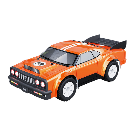
1/16 UDISPORT DRAG BATTLE TOP FUEL
OPERATING
INSTRUCTIONS
FULL PROPORTIONAL REMOTE CONTROL UDIRACING SERIES
Our company's products are improving all the time,design and specifications are subject to
Important
change without notice. All the information in this manual has been carefully checked to ensure
Notice
accuracy, if any printing errors, our company reserve the final interpretation right.
UD1609 / UD1609PRO
This product is suitable for users over 14 years old.
Please read this instruction manual carefully befores use.
V1.0
Advertisement

Subscribe to Our Youtube Channel
Summary of Contents for udir/c UD1609
- Page 1 UD1609 / UD1609PRO 1/16 UDISPORT DRAG BATTLE TOP FUEL OPERATING INSTRUCTIONS FULL PROPORTIONAL REMOTE CONTROL UDIRACING SERIES V1.0 This product is suitable for users over 14 years old. Please read this instruction manual carefully befores use. Our company's products are improving all the time,design and specifications are subject to Important change without notice.
- Page 2 THANK YOU ● Thank you for choosing this product. The remote control model is designed to be fun to drive and uses high quality parts to improve durability and performance. The instruction manual you are reading is to make the product easier to understand and explain more thoroughly.
- Page 3 WARNING Before Operation ● Read the instruction manual in detail, or ask for the person with experience in operation, and read with the guardian if necessary. ● Make sure all screws and nuts are properly tightened. ● The remote control and the vehicle should always use the battery with saturated power to avoid losing control of the model.
-
Page 4: Product Maintenance
Product maintenance When not in use, remove Please remove the sediment the battery from the and dirt on the car model and transmitter. completely and must be kept dry after play. Apply lubricating Please separate oil to external the car and battery metal parts. - Page 5 Model Car Summary The picture is only for reference, please make the object as the standard. 1601-015 Regular version 1609-006 1609-008 1609-004 1805-004 Power switch 1601-007 1806-003B 1601-011 1601-035 1604-010 1609-004 1805-003 Professional version 1805-005 S1701 1601-025 1601-028 1601-018 1601-027 1601-012 1601-013 ESC01W...
- Page 6 1609-001 1609-001 1601-002 1609-002 1609-002...
-
Page 7: Electronic Speed Controller
Electronic speed controller 1601-011 Antenna Lights Steering servo Power switch Motor Model Battery ESC01W Steering servo Model Battery Motor Power switch Lights Antenna... - Page 8 Preparation of transmitter Transmitter function Default steering main interface wheel direction Turn left / Turn right Power switch Car lights control button Default throttle trigger The car lights color mode can be switched and the car lights can direction be switched off. Forward / Backward / Brake Throttle speed limit switch Low speed mode:...
- Page 9 Adjustment of gyroscope action ratio This product has the function of ESP car stability system, which can effectively correct the car attitude and direction when the car skids or loses control. The function and sensitivity of the car gyroscope sensor can be adjusted through the ESP knob of the transmitter. The action ratio The action ratio decreased...
- Page 10 Assembly of the transmitter battery Battery Cover Note Direction. 1.5V×4 AAA Batteries(not included) Open battery cover at the bottom of transmitter. Install batteries. Follow the direction of batteries designated in the inside of the battery box. Model Battery charging The battery contains less power when leaving the factory, Connect the attached charger with the model battery charging so it must be charged and saturated before use.
-
Page 11: Operational Guidance
2) Pull out the clips, and remove the battery hold-down. Output 3) Put the battery into the battery input port port Model Battery compartment, Battery hold-down reset clips reset and then connect 4) Reset the bodyshell with the ESC. Operational guidance Frequency matching 1>... - Page 12 1601-011 Power on method Press for 2 second to turn on the power. The lights flash and enter the frequency matching state. Press for 2 second to turn off the power. 1601-011 ESC01W Power on method Press for 2 second to turn on the power. The lights flash and enter the frequency matching state.
- Page 13 Steering wheel Steering wheel Turn left Turn right Turn left and move forward Turn right and move forward Throttle trigger Steering wheel Throttle trigger Steering wheel Go forward Turn left Go forward Turn right Turn left and move backward Turn right and move backward Throttle trigger Steering wheel Throttle trigger...
- Page 14 Assembly diagram of spare parts The picture is only for reference, please make the object as the standard. Wheels 1601-018 1601-022 1601-016 Wheel 1601-004 Shock absorbers...
- Page 15 Assembly of front suspension arm 1601-025 1601-050 1601-023 1601-022 1601-021 1601-018 1601-019 1609-005 1601-017 1601-026 1601-025 Assembly of rear suspension arm 1601-027 1601-028 1601-050 1601-022 1601-021 1601-017 1601-026 1601-018 1601-051 1601-028...
- Page 16 Assembly of front bumper 1604-010 1609-008 1601-064 1601-055 1601-034 1601-039 1601-035 1601-056 1604-010...
- Page 17 Anti-roll wheel 1609-006 1609-008 1601-064 1601-055 1601-034 1601-054 1609-006 1601-035 1601-039 1601-056 Assembly of front(rear) differentials 1805-013...
- Page 18 Assembly of steering servo 1601-024 1601-032 Steering servo 1601-024 1601-031 1601-031 1601-030 1601-031 1601-033 Upper chassis 1601-056 1609-008 1601-060 1601-049 1609-008 1601-034 1601-034 1601-015 1601-054 1601-054 1601-054 1601-062 1601-024 1601-056 1601-024 1601-013 1601-060...
- Page 19 Main propeller shaft system 1601-036 1601-017 1601-021 1601-041 1601-038 1601-017 Assembly of chassis 1601-056 1601-056 1601-054 1601-062 1601-056 1601-053...
- Page 20 Buyable accessories The picture is only for reference, please make the object as the standard. 1609-001A 1609-001B 1601-002 1609-002 Body assembly Body assembly Body clips × 4 Front and rear light groups 1805-004 1805-003 1806-003B 1806-003A Wheel × 2 Wheel × 2 Wheel ×...
- Page 21 1601-018 1601-023 1609-005 1601-025 Front & Rear wheel Front CVD driveshaft Adjustable steering linkage Suspension arms (front) carriers assembly assembly × 2 1601-027 1601-028 1805-013 1601-030 Rear driveshaft Suspension arms (rear) Differential assembly Servo saver assembly × 2 1601-031 1601-032 1601-034 1601-035 Steering bellcrank...
- Page 22 1601-046 1609-006 1601-045 1601-047 Hexagon nut wrench Anti-roll wheel Cross screwdriver Hex wrench 2-4mm 1601-048 1601-049 1601-050 1601-051 Ø2.5×11.8mm PM Ø2.5×5mm PM Ø2×13mm PM Ø2.5×16.5mm PM Shoulder screws ×8 Screws ×8 Screw pin set ×8 Screw pin set ×8 Only for 390 motor mounts 1601-052 1601-053 1601-054...
- Page 23 1601-017 1601-021 1601-019 1601-024 Ø8×Ø4×3mm Ø12×Ø8×3.5mm Ø2.5×10mm Ø2.5×12mm Ball bearing ×4 Ball bearing ×4 Pivot balls ×4 Pivot balls ×4 1601-022 1601-026 1601-033 Ø1.8×6.8mm Ø2.5×32mm Ø2.5×21mm Pin ×4 Pin ×4 Pin ×4...
-
Page 24: Fcc Note
FCC Note This equipment has been tested and found to comply with the limits for a Class B digital device, pursuant to Part 15 of the FCC Rules. These limits are designed to provide reasonable protection against harmful interferencein a residential installation. This equipment generates uses and can radiate radio frequency energy and, if not installed and used in accordance with the instructions, may cause harmful interference to radio communications.
Need help?
Do you have a question about the UD1609 and is the answer not in the manual?
Questions and answers