Table of Contents
Advertisement
Advertisement
Table of Contents

Related Manuals for Firefly VEGATOUCH LYRA Coach House V3

Summary of Contents for Firefly VEGATOUCH LYRA Coach House V3
- Page 1 Coach House V3 OEM Manual...
-
Page 2: Table Of Contents
Coach House V3 OEM Manual The information contained in this manual is a general overview of the Firefly system and is subject to change at any time. Table of Contents Lyra Screen Navigation Home Lights Auto Gen Start Settings (AGS) -
Page 3: Lyra Screen Navigation
Lyra Screen Navigation Tap any icon from the navigation bar to select the desired page. The currently selected page will always be listed in the top corner of the screen. Home Lights Climate Settings Navigation Menu... -
Page 4: Home
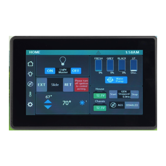
Home The Light Master controls all interior lights at once. When Light Master Off is pressed, it will remember which lights were on. Then, when Light Master On is pressed, it will only turn on the lights that are in memory. - Page 5 These graphics represent the percentage filled for holding tanks. The LP Tank readings are as follows: Disconnected – above 97%. Percentage changes to Disc and tank shows empty. Full – 75% to 97%. Percentage changes to Full and tank shows accurate level. Actual Level –...
-
Page 6: Lights
Lights This screen will control the lighting for the entire coach, including the exterior. Tap any button to turn the desired light On/Off. Lights with up/down arrows are dimmable. Press and hold these buttons to ramp the brightness up or down. -
Page 7: Auto Gen Start Settings (Ags)
Auto Gen Start Settings Tap to Enable/Disable AGS (as described on page 5). Trigger Options – Automatically start the generator using specified voltage settings (Low Volts) or when A/C or Heat Pump starts (HVAC). Select one or both triggers. If no triggers are selected, AGS will not run. Disable HVAC Load while connected to shore power to keep the generator from starting. -
Page 8: Climate Control
Climate Control Use the Arrows to select your Current Temperature/Mode/Fan speed. desired temperature by zone. Fan Mode – The fan will operate by choosing High or Low. Auto will turn the fan off. Fan Mode is only available if HVAC is off. Cool –... -
Page 9: Settings
Settings Tap to enter the Network Diagnostics page. Navigate to the Switch Panel Info page. Tap to enter the Vegatouch Mira connection screen. Floorplan display. Tap to select between 10 levels of Screen Brightness and Off. When Auto Dimming is enabled, the screen will enter sleep mode after 60 seconds of inactivity. Tap anywhere on the screen to wake it up. -
Page 10: Settings/Mobile App
Settings/Mobile App Vegatouch Mira is a wireless control module that easily connects to any Android or iOS device to give total control to many electrical, electronic and mechanical systems in your coach. Pair any device with the coach’s built-in interface to monitor and control these systems. -
Page 11: Settings/Network Diagnostics
Settings/Network Diagnostics This screen will show the status of the Lyra screen and the G12 panel. It will also display any current faults the system is experiencing. Tap the tabs at the bottom of the screen to visit the different diagnostic pages. - Page 12 This screen will show which G12 Outputs are currently active. Active Output This screen will show the current status of the Aircons and Vent Fan Controllers. Main Vent Fan Controller Disconnected.
-
Page 13: Settings/Switch Panel Info
Settings/Switch Panel Info The color-coded Wireless Graphic and Signal Strength Value will identify the status of a wireless switch panel. • Green – Over 100 (Strong) • Yellow – 85-100 (Medium) • Red – Less than 85 (Weak) Red Wireless Graphic with a Zero reading – The switch is currently disconnected from the screen. It is likely that the battery inside your switch panel needs replaced. -
Page 14: Floorplan Selection And Options
Floorplan Selection and Options Press and hold the floorplan box for 7 seconds to enter the Floorplan/Options selection screen. From here, you’ll be able to select the correct floorplan and any options that are specific to the coach. -
Page 15: Wireless Switch Pairing
Wireless Switch Pairing Red switch indicator with a zero reading – The switch is currently disconnected from the screen. It is likely that the battery inside your switch panel needs replaced. The wireless switch panel in your coach will illuminate a green LED whenever a button is pressed. If the LED on your switch panel does not illuminate when you press a button on your switch, you will need to replace the 2032 coin cell battery. -
Page 16: Service Mode
Service Mode This system features a Service Mode to be used by qualified technician. Once enabled, it will remove the 5-second hold delays on: • Gen Hours Reset • Individual Wireless Switch Pairing • Clear All Wireless Switch Pairing • Floorplan Selection To enable Service Mode, Press and hold the Settings button for 5 seconds until a yellow wrench appears at the top right-hand corner of the screen (next to the time). -
Page 17: Vegatouch Mira Modules
If the floorplan is blank, Mira won’t be able to connect. The network cable could also be faulty. Inspect the cable at both ends and replace it if necessary. If the cabling and setup seem to be correct, contact Firefly Integrations about possibly replacing the Mira module. -
Page 18: Mira Setup
Mira Setup Notice: Make sure that Bluetooth is turned ON in your smart device settings before proceeding. Locate the Login Information: The login information can be found by clicking on the Mobile App button on the settings page of the touchscreen or from the Mira module’s label. - Page 19 Notice: iOS Setup Tips Turn on Bluetooth to allow Vegatouch Mira to connect to Accessories. If you do not have Bluetooth turned ON in your iOS settings, you will see this screen. Do not click OK, you must click SETTINGS. Your Bluetooth Settings page will now appear, and you should turn Bluetooth ON.
- Page 20 App Settings: Access the App Settings page by tapping the triangle (at the bottom of the screen) to expose the Settings button. Tap the gear to visit the settings page. Tap the Temperature Units selection to choose between Fahrenheit and Celsius. System Information and Mira Name.
- Page 21 Diagnostic Tools: Tap to display a list of currently connected devices. Remote Help is available by calling Firefly Integrations. Do not enable remote help without consultation.
-
Page 22: Ssp17 Switch Panels
SSP17 Switch Panels Your coach uses SSP17 switch panels to control lighting and other functions. Lights that are dimmable will have Up/Down arrows next to the icon. Press and hold these buttons to ramp the brightness up and down. Each time that a button is pressed, the Operational LED will illuminate green to indicate that the command has been sent to the touchscreen. -
Page 23: G12 Dc Panels
G12 DC Panel Your G12 control panel is the power distribution center for the coach. This panel receives the signals sent from your switch panels and performs the actions that have been requested by activating and deactivating the required circuits. Every circuit controlled by the G12 is numbered and listed on a black label (load list) which is usually mounted next to the G12 panel. -
Page 24: Networking
Networking Your distribution panel and touchscreen are connected via your coach’s RV-C network. Each component will have a NET LED that is used to show network status. If a NET LED is displaying anything other than solid green and some of the panel’s functions are not working, please contact your manufacturer for Technical Support. -
Page 25: Network Status Indicators
Network Status Indicators Every component of the Firefly system uses an LED to communicate network status. Use the key below to determine the network status of your hardware. Panel Network Status Indicator – Applies to any device with a network indicator: Fast flashing Green Light (4 times/sec) –... -
Page 26: Mira Net Led Status Key
Mira NET LED Status Key The NET LED on your Mira module can change color in different situations. Use the following key to determine the operational status of your module. Device has no power or has completely failed Fast flashing green (4 times/sec) Device is attempting to make initial connection to the CAN network and good files Solid green...
Need help?
Do you have a question about the VEGATOUCH LYRA Coach House V3 and is the answer not in the manual?
Questions and answers
When house battery is disconnected for winter storage will the firefly rest by itself?