Table of Contents
Advertisement
Quick Links
Advertisement
Table of Contents

Subscribe to Our Youtube Channel
Summary of Contents for Omega OTEC IEWQ Series
- Page 1 IEWQ/ICHQ Series High Wall Inverter Installation Manual...
-
Page 2: Table Of Contents
Table of Contents Part Ⅰ : Technical Information ...............1 1. Summary ........................1 Part Ⅱ : Installation and Maintenance ..........2 2. Notes for Installation and Maintenance ..........2 3. Installation ........................5 3.1 Installation Dimension Diagram ................5 3.2 Installation Parts-checking ................7 3.3 Selection of Installation Location ..............7 3.4 Requirement For Electric Connection ............7... -
Page 3: Part Ⅰ : Technical Information
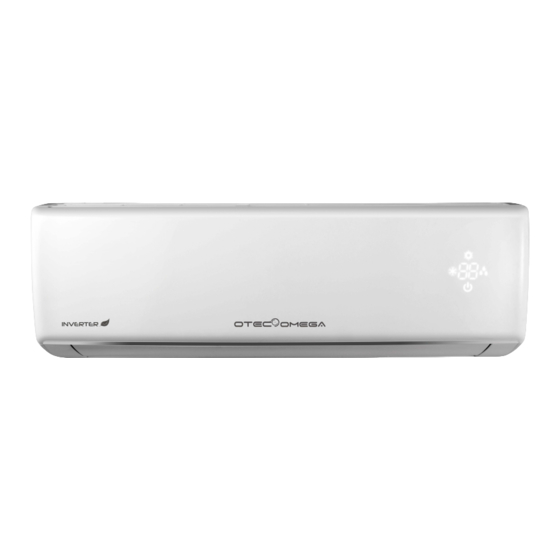
Part Ⅰ : Technical Information 1. Summary Indoor Unit IEWQ036J3A-RWI100 Outdoor Unit ICHQ036J3A-RLH100 Remote Controller: Technical Information... -
Page 4: Part Ⅱ : Installation And Maintenance
Part Ⅱ : Installation and Maintenance 2. Notes for Installation and Maintenance Safety Precautions: 10. If the power cord or connection wire is not long enough, please get the specialized power cord or connection wire Important! from the manufacture or distributor. Prohibit prolong the wire by yourself. - Page 5 connection pipe is not yet connected, air will be sucked in and cause pressure rise or compressor rupture, resulting in injury. ●Prohibit installing the unit at the place where there may be leaked corrosive gas or flammable gas. If there leaked gas around the unit, it may cause explosion and other accidents.
- Page 6 Main Tools for Installation and Maintenance 1. Level meter, measuring tape 2. Screw driver 3. Impact drill, drill head, electric drill 4. Electroprobe 5. Universal meter 6. Torque wrench, open-end wrench, inner hexagon spanner 7. Electronic leakage detector 8. Vacuum pump 9.
-
Page 7: Installation
3. Installation 3.1 Installation Dimension Diagram Space to the wall Space to the wall At least 15cm At least 15cm Drainage pipe Installation and Maintenance... - Page 8 Installation procedures Start installation Preparation before installation Read the requirements select installation Prepare tools for electric connection location Select indoor unit Select outdoor unit installation location installation location Install the support of outdoor unit Install wall-mounting (select it according to the actual situation) frame, drill wall holes Connect pipes of indoor Fix outdoor unit...
-
Page 9: Installation Parts-Checking
3.4 Requirement For Electric Connection 3.2 Installation Parts-checking 1. Safety Precaution Name Name (1) Must follow the electric safety regulations when installing Indoor unit Sealing gum the unit. Outdoor unit Wrapping tape (2) According to the local safety regulations, use qualified Support of outdoor power supply circuit and air switch. - Page 10 in the holes. 4. Outlet Pipe (3) Fix the wall-mounting frame on the wall with tapping screws (1) The pipe can be led out in the direction of right, rear right, (ST4.2X25TA) and then check if the frame is firmly installed by left or rear left.(As show in Fig.3) pulling the frame.
- Page 11 (4) Put wiring cover back and then tighten the screw. (5) Close the panel. Drain hose Outlet pipe Note: (1) All wires of indoor unit and outdoor unit should be connected by a professional. Tape Drain hose (2) If the length of power connection wire is insufficient, please Outlet Fig.9 pipe...
-
Page 12: Installation Of Outdoor Unit
4. Connect Indoor and Outdoor Pipes Outdoor Indoor (1) Remove the screw on the handle and valve cover of outdoor Fig.17 Wall pipe Sealing gum unit and then remove the handle and valve cover.(As show in Fig.21) Upper hook (2) Remove the screw cap of valve and aim the pipe joint at the bellmouth of pipe.(As show in Fig.22) Liquid pipe Pipe joint... -
Page 13: Vacuum Pumping And Leak Detection
2. Leakage Detection The drain hos (1) With leakage detector: can't raise upwards Check if there is leakage with leakage detector. (2) With soap water: If leakage detector is not available, please use soap water for leakage detection. Apply soap water at the suspected position Wall Fig.25 and keep the soap water for more than 3min. - Page 14 OMEGA IEWQ(HQ) High Wall Inverter Installation Manual info@otecomega.com info@otecomega.com www.otecomega.com www.otecomega.com IEWQ(CHQ)I3A-IM1R0622...


Need help?
Do you have a question about the OTEC IEWQ Series and is the answer not in the manual?
Questions and answers