Table of Contents
Advertisement
Quick Links
Advertisement
Table of Contents

Subscribe to Our Youtube Channel
Summary of Contents for M-Audio ACCENT MODULE MIK1
- Page 1 ACCENT MODULE MIK1 SERVICE MANUAL...
-
Page 2: Table Of Contents
Contents Fe atures............................Connection.......................4 General Exploded Drawing and List....................5 Circuit Boards..........................6 Parts List............................PCB Boards..........................Diagnosis............................Frequently Asked Questions...................... Spare Part List.......................... -
Page 3: Features
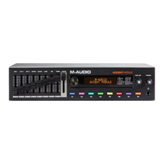
Features Connect any USB MIDI or 5-pin MIDI controller to create music without the need for a laptop 20 built-in voices, with the ability to split or layer two voices simultaneously Includes AIR Steinway® Piano and AIR Structure samples ... -
Page 4: Connection
Connection Main board to other board connection Main board other board Phones and Main board CN2 Funciton board CN8 Funciton board CN3 Encoder board CN3 Headphone interface board CN1 Potentiometer board CN1 LCD display board... -
Page 5: General Exploded Drawing And List
General Exploded Drawing and List remark... -
Page 6: Circuit Boards
Circuit Boards Main Board Schematic-01... - Page 7 Circuit Boards Main Board Schematic-02...
- Page 8 Circuit Boards Main Board Schematic-03...
- Page 9 Circuit Boards Main Board Schematic-04...
- Page 10 Circuit Boards Main Board Schematic-05...
- Page 11 Circuit Boards Main Board Schematic-06...
- Page 12 Circuit Boards Main Board Schematic-07...
- Page 13 Circuit Boards Main Board Schematic-08...
- Page 14 Circuit Boards Main Board Schematic-09...
- Page 15 Circuit Boards Function Board Schematic...
- Page 16 Circuit Boards O ther Board Schematic SLIDER +3.3VA_DA SLIDER0 SLIDER1 +3.3VA_DA SLIDER2 11 pin/2.5 SLIDER3 SLIDER0 SLIDER1 SLIDER2 SLIDER3 SLIDER4 SLIDER4 SLIDER5 SLIDER6 SLIDER7 SLIDER5 MASTER_VOL SLIDER6 SLIDER7 MASTER_VOL...
- Page 17 Level Material Coding Subunit Description Subunit specification Qty. Unit Remark Unpacking part of the Stage Piano 1020107320 MIK1 1 PCS Module 1010112640 Main board ASSY ACCENT MODULE(MIK1) 1 SET 6200200240 Stereo jack ST-222-06W 11pin WEALTH METAL 1 PCS 6200200200 Stereo jack 6PIN 6.35mm L=33mm with screws 2 SET J2 J4...
-
Page 18: Parts List
Parts List ++++ 603010126 CAP SMD 150pf/50V +5%-5% 0603 4.04 PCS C42-43 C90-91 ++++ 603010186 CAP CERAMIC SMD 2200PF/50V ±5% 0603 SMD 4.04 PCS C132-133 C166 C176 ++++ 603010040 CAP CERAMIC SMD 22pf/50V +5% -5% 0603(COG) SMD 7.07 PCS C55-58 C62 C229 C263 ++++ 603010078 CAP CERAMIC SMD... - Page 19 Parts List ++++ 6010105360 IC SMD PS9117A-F3-A (500330003700) 1 PCS ++++ 602030005 Resistor chain SMD 10K ohm(1/16w)+5%-5% CRN164 3.015 PCS AR3 AR5 AR7 ++++ 602010009 Resistor SMD 100 ohm(1/16w)+1%-1% 0603 2.02 PCS R31-32 ++++ 602010021 Resistor SMD 100K ohm(1/16w)+1%-1% 0603 2.02 PCS R141-142 ++++...
- Page 20 Parts List 631010052 Dustproof mesh 130*64*0.2mm black 1 PCS Φ2.6*6PB black crisscross flat tail tapping 301020007 Flat round head screws PB 19 PCS for PCB 206010202 Button3 ABS N/A RD101426 8 PCS 305020001 Top cabinet SECC T=1.0mm spray powder matted black 1 PCS SECC T=1.0mm spray powder matted black 306100002...
-
Page 21: Pcb Boards
PCB Boards Main Board-T op... - Page 22 PCB Boards Main Board-Bot t t om...
- Page 23 PCB Boards V ol um e Board Function Board...
- Page 24 PCB Boards O th e r Board...
-
Page 25: Diagnosis
Diagnosis System Self-test Operating Instruction System self-test function could assist you to make a comprehensive check with these functions: LED, DAC, ADC, USB port, function keys, keys, pedals, and RAM, ROM of A5 chip. Before power on, please follow the procedure below: ... - Page 26 Diagnosis Introductions on Test Items Test1: Nor Flash test When having this test, an increasing percentage will be shown in the middle of the LED, such as 15%, representing the Nor Flash data interface and internal storage check have finished 15%: 01/15 NorFlash Checking: 15% When the check is down, the LED will show the result, like OK,representing data in Norflashl is...
- Page 27 Diagnosis If you are having a complete system self test (press B1, B2, and B5), then the checksum in hex system will appear in the LED. For example, 1234 H means the checksum is 1234. 02/15 NorFlash Finished: 1234 H ...
- Page 28 Diagnosis Teat3: SDRAM test When having this test, an increasing percentage will be shown in the middle of the LED, , like: 25%, representing SDRAMcheck has finished 25%: 04/15 SDRAM Checking: 25% If there is no errors in SDRAM, OK will appear in the LED. 04/15 SDRAM Finished: OK.
- Page 29 Diagnosis Reverb-Max Set [Reverb] slider (Reverb volume slider) to the highest position. Chorus-Min Set [Chorus] slider (Chorus volume slider) to the lowest position. Chorus-Max Set [Chorus] slider (Chorus volume slider) to the highest position. Bass-Min Set [Bass] slider (Bass volume slider) to the lowest position. Bass-Max Set [Bass] slider (Bass volume slider) to the highest position.
- Page 30 Diagnosis 06/15 Slider Checking: Press Dail When the dial is pressed correctly, it will automatically switch to the final complete interface of currently test item: 06/15 Slider Finished: OK. In the current test, press [B2] or turn the dial in clockwise direction to enter the next test item. ...
- Page 31 Diagnosis When the item is testing, you can only turn the dial in clockwise direction to enter the next test item. When finished, press [B2] or turn the dial in clockwise direction to enter the next test item. You can only recheck this item by pressing the dial.
- Page 32 Diagnosis Info. Explanation LED goes red Green LED goes green Blue LED goes blue LED goes white The final complete interface of currently tested item will appear until all these four color have been lightened: 09/15 LED Finished: In the current test, press [B2] or turn the dial in clockwise direction to enter the next test item. ...
- Page 33 Diagnosis 11/15 Auxin Auxin Inserted! In the current test, press [B2] or turn the dial in clockwise direction to enter the next test item. Press [B8] button or the dial to recheck this item. Test11: Aux out test This test is realized by sending sine wave 1KHz and 600mV to the left and right channels of different sounding or Aux out device respectively.
- Page 34 Diagnosis 13/15 Phones Checking: <-- Left Info. Explanation <-- Left Left channel is sounding Right --> Right channel is sounding The final complete interface will appear when both channels have been tested: 13/15 Phones Finished: In the current test, press [B2] or turn the dial in clockwise direction to enter the next test item.
- Page 35 Diagnosis means the USB flash drive cannot open or be established correctly: 14/15 Udisk Finished: Open ERR. Error messages Explanations Open ERR. Cannot open or be established correctly. Write ERR. Cannot write file. Read ERR. Cannot read file. Data ERR. Read and Write functions, but disparity in content.
-
Page 36: Frequently Asked Questions
Frequently Asked Questions Problem Possible Cause and Solution Nothing on the LCD when powered on. Please update firmware. Function key issues Please take Test6 to check all the keys. Knob issues Please take Test7 to check all the knobs. Dial issues Please take Test5 to check Dial function. -
Page 37: Spare Part List
Spare Part List LAYER PART NO PART NAME PART SPECIFICATION UNITAGE PHOTO REMARK Main board ACCENT 1010112640 1.00000 SET ASSY MODULE(MIK1) Potentiometer 1019902550 MIK1 1.00000 SET board ASSY Encoder 1019902560 MIK1 1.00000 SET board ASSY Volume board 1010701290 MIK1 1.00000 SET ASSY Function 1010305030... - Page 38 Spare Parts List 1.00000 PCS ++++ 6180001210 LCD module 2002A Amber light 5V AL oxidation black φ 318030004 Metal knob 1.00000 PCS 16.8*16.8mm ABS injection Pantone 299010129 Fader cap 9.00000 PCS process black C N/A ABS+TPE injection ABS 20801007101 Volume knob Cool grey8C+TPE black 2.00000 PCS N/A after change mould...
- Page 39 Spare Parts List Two sides 6pin L=60mm 26# Two Gray flat 628071912 sides with 6pin/2.0mm 1.00000 PCS cable with cathode plug cathode plug Two sides 10pin L=80mm 26# Two with gray flat 1.00000 PCS 628071911 sides with 10pin/2.0mm cable with cathode plug cathode plug 16pin L=80mm one side...
Need help?
Do you have a question about the ACCENT MODULE MIK1 and is the answer not in the manual?
Questions and answers