
Summary of Contents for Harman AMX HPX-1600
- Page 1 IN ST ALLATI O N M A NU AL R E T RA C T A B LE C O N N E C T I O N PO R T A N D H PX M O DU LES HPX-1600...
- Page 2 IMPORTANT SAFETY INSTRUCTIONS READ these instructions. KEEP these instructions. HEED all warnings. FOLLOW all instructions. DO NOT use this apparatus near water. CLEAN ONLY with dry cloth. DO NOT block any ventilation openings. Install in accordance with the manufacturer's instructions. DO NOT install near any heat sources such as radiators, heat registers, stoves, or other apparatus (including amplifiers) that produce heat.
-
Page 3: Table Of Contents
Table of Contents Table of Contents HPX-1600 HydraPort ..................1 Overview ........................... 1 Common Application ......................1 Product Specifications ....................1 HPX-1600 Exploded View....................3 Installing the HPX-1600 ...................4 ATTENTION READ THIS FIRST!..................4 Step 1 - Select an Installation Location ................4 Installation Location Notes ........................ -
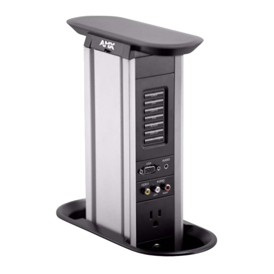
Page 4: Hpx-1600 Hydraport
HPX-1600 HydraPort HPX-1600 HydraPort Overview The HPC-1600 HydraPort Retractable Connection Port (FG550-xx, see models available in the Product Specif ications on page 1) is the first completely modular, retractable cable connection system built to accommodate the diverse connection needs of conference and meeting room visitors. - Page 5 HPX-1600 HydraPort HPX-1600 Specif ications Models Available: • International, Black trim (FG550-BL) • International, Silver trim (FG550-SL) • North American, Black trim (FG550-01-BL) • North American, Sliver trim (FG550-01-SL) Enclosure Natural finish metal frame with plastic top and bottom covers moving vertically in a plastic sleeve assembly.
-
Page 6: Hpx-1600 Exploded View
HPX-1600 HydraPort HPX-1600 Exploded View FIG. 2 provides an exploded view of the HPX-1600 HydraPort System, with the main components referenced in this document labeled. Use this diagram for reference while following the instructions provided in this document. Top Cover HPX-1600 Chassis Aluminum Frame Module Faceplates... -
Page 7: Installing The Hpx-1600
Installing the HPX-1600 Installing the HPX-1600 ATTENTION READ THIS FIRST! WARNING: Only a professional, AMX-qualif ied installer should perform this installation. and the installation must conform to all local codes. This product may not be installed by the end-user. A typical installation will include several of various available modules listed in the Product Specif ications section on page 1. Each of these modules has specific instructions for terminating their rear connections. -
Page 8: Installation Location Notes
Installing the HPX-1600 Installation Location Notes The HydraPort system requires a mounting surface from 19mm (.75in) to 50mm (2.0in) thick. The HydraPort system requires at least 383mm x 293mm x 159mm (zzin x xxin x yyin) of space below the mounting ... -
Page 9: Step 3 - Prepare The Terminations
Installing the HPX-1600 Install the router guide bushing into the base of a suitable router. The router should be equipped with a ½ inch (12.2mm) collet and a baseplate capable of accepting a standard 1 3/16 inch (30.2mm) guide bushing. Install the router bit into the router with an appropriate portion of the bit exposed below the guide bushing. - Page 10 Installing the HPX-1600 Note that for terminations for which the far end of the cable is not accessible either because the cable has been run under carpet, in a conduit or structure, or is otherwise fixed, the cable must be placed through the retaining ring, (note the orientation of the retaining ring - see FIG.
-
Page 11: Step 4 - Insert The Modules
Installing the HPX-1600 Step 4 - Insert the Modules IMPORTANT: See Step 4.6 for the installation of High Voltage Isolators (HPX-PA-HVI) These Isolators must be installed properly to maintain product safety certif ications. NOTE: All Low-Voltage, Secondary-Circuit (LVSC) Modules must be installed above the AC Power Outlets and Circuit Breaker Modules in the HPX-1600 Base Assembly. - Page 12 Installing the HPX-1600 Slide the pre-terminate modules one at a time into the Base assembly. Note the orientation of each module: a small tab exists on the bottom side (shown facing up in FIG. 10) of the faceplate of each module. Ensure this tab is facing the bottom side of the system (see FIG. 11 on page 10). This tab on each Module faceplate must face the BOTTOM of the HydraPort system (bottom)
- Page 13 Installing the HPX-1600 For AC power modules, plug the provided wire harness into the Power Inlet assembly inside the bottom cover (FIG. 11). Cross-section view of Bottom Cover Bottom Cover showing cable routing (inside view) Bottom Cover - Connect Each AC Power Module to the Power Inlet Assembly FIG.
-
Page 14: Step 5 - Install The Bottom Cover
Installing the HPX-1600 Step 5 - Install the Bottom Cover Once all of the desired modules are installed, complete each face of the system with blank modules. At least 3M (3") of blank modules will be used at the bottom of the system to correspond to that portion of the system that is always below the mounting surface, even when the system is deployed in the up position (FIG. - Page 15 Installing the HPX-1600 Ensure each AC power module is connected to the power inlet assembly and that the circuit breaker is also connected to the power inlet assembly (FIG. 13). AC Power connector Circuit Breaker Connector AC Power connector AC Power connector Bottom Cover (inside view) AC Power connector...
-
Page 16: Step 6 - Install The Lift Spring Assemblies
Installing the HPX-1600 Secure the cables exiting the bottom cover using the provided wire ties (FIG. 15). Cable Cable Wire Tie Wire Tie Bottom Cover (secured with 4 mounting screws) HPX-1600 Chassis Aluminum Frame (bottom) Bottom Cover - Installed with Cables Exiting and Secured FIG. - Page 17 Installing the HPX-1600 Take hold of the body of one lift spring assembly and pull it firmly up so that it can be snapped into the provided slot in the bottom cover (FIG. 17). Notch on Lift Spring Assembly The notch on the Lift Spring Assembly fits into the slot on the Bottom Cover Slot on Bottom Cover Lift Spring Assemblies...
-
Page 18: Step 7 - Install The System Into The Mounting Surface
Installing the HPX-1600 Step 7 - Install the System Into the Mounting Surface Turn the system over and install the unit into the cutout in the mounting surface (FIG. 18). Mounting Surface Mounting Sleeve HPX-1600 Chassis Aluminum Frame (bottom) Module Faceplate Spring Lift Assembly Spring Lift Assembly Completed Assembly Latched in the Closed Position... -
Page 19: Step 8 - Install The Retaining Ring
Installing the HPX-1600 Step 8 - Install the Retaining Ring Insert the four #6-32 x 1 3/8 retaining screws into the retaining ring. Note the orientation of the retaining ring. This orientation changes in order to accommodate the various thicknesses of mounting surfaces (see FIG. - Page 20 Installing the HPX-1600 FIG. 20 shows the HPX-1600 Unit installed in to the mounting surface: Bottom View Top View HPX-1600 Installed in Mounting Surface FIG. 20 HPX-1600 Retractable Connection Port...
-
Page 21: Step 9 - Install Power Cord (If Required)
Installing the HPX-1600 Step 9 - Install Power Cord (If Required) If AC power modules are to be used in International models (FG550-BL, FG550-SL), install a suitable 14AWG power cord into the provided IEC 320 C14 socket. North American models (FG550-01-BL, FG550-01-SL) include a pre-attached power cord with metal retention bracket. If this bracket has been removed during installation, reinstall it at this time. -
Page 22: Step 10 - Install Shields
Installing the HPX-1600 Step 10 - Install Shields Secure the two shields to each other using the 8 supplied screws. Ensure that any fixed cables pass through the assembled shield appropriately. Snap the assembled shield onto the lower portion of the mounting sleeve. Install the four additional mounting screws into the top of the shield to secure the shield to the mounting sleeve (FIG. -
Page 23: Step 11 - Secure Cables
Installing the HPX-1600 Step 11 - Secure Cables Terminate the backside connections as required for each cable exiting bottom of the HPX-1600. Secure these cables and the power cable to the four tabs provided on the retaining ring using the supplied wire ties (FIG. 23). Tabs/Wire Ties (2 on each side) Mounting Surface Retaining Ring... -
Page 24: Hpx-P200-Xx Power Outlet Module
HPX-P200-xx Power Outlet Module HPX-P200-xx Power Outlet Module Overview The HPX-P200-xx HydraPort Power Outlet Module is designed to be used in conjunction with the HPX-1600 HydraPort Base Assembly. The HPX-P200-XX Power Outlet Assembly provides user accessible AC "Mains" Power to the front panel of the HydraPort System (FIG. -
Page 25: Installing The Hpx-P200-Xx Power Outlet Module
HPX-P200-xx Power Outlet Module Installing the HPX-P200-XX Power Outlet Module WARNING: Disconnect the IEC C-14 Power Inlet Connector On the HydraPort Base Assembly Ensure that the AC Power cord is disconnected from IEC C-14 power inlet connector on the HydraPort Base Assembly prior to disassembly of the HydraPort Base assembly or installation of the HPX-P200-XX Power Outlet Module (see FIG. -
Page 26: Step 2 - Insert The Power Outlet Module Into The Hpx-1600 Chassis
HPX-P200-xx Power Outlet Module Step 2 - Insert the Power Outlet Module Into the HPX-1600 Chassis Insert the HPX-P200-XX Power Outlet Module into the main chassis of the HPX-1600 Base Assembly. Note the position of module interlock tab: this tab should face towards the bottom of the HPX-1600 Base assembly when installed in its mounted position (FIG. -
Page 27: Step 3 - Install The 10 Amp Circuit Breaker (Included With Hpx-Pak-Xx Accessory Kit)
HPX-P200-xx Power Outlet Module Step 3 - Install the 10 Amp Circuit Breaker (Included with HPX-PAK-XX Accessory Kit) A HydraPort Power Accessory Kit (HPX-PAK-XX) is required for the HPX-P200-XX Power Outlet Module to be functional. This power accessory kit provides a 10 Amp circuit breaker for the HydraPort System to prevent power overload and complete the AC Power Circuit. -
Page 28: Hpx-Pa-Hvi High Voltage Isolator
HPX-PA-HVI High Voltage Isolator HPX-PA-HVI High Voltage Isolator Overview The HPX-PA-HVI High Voltage Isolator (FG559-33) is designed to be installed in the HPX-1600-xx-xx Hydraport Retractable Connection Port to separate the AC Mains Power from low-voltage, secondary-circuits (FIG. 29). HPX-PA-HVI (Folded for Installation) FIG. -
Page 29: Step 3 - Insert The High Voltage Isolator
HPX-PA-HVI High Voltage Isolator Step 3 - Insert the High Voltage Isolator Insert the High Voltage Isolator into the HPX-1600 Base Assembly so that the low-voltage, secondary-circuit cables exiting the chassis are trapped along the sides of the chassis. See Figures FIG. 30 and FIG. 31. Position top of High-Voltage Isolator here Trim High-Voltage... -
Page 30: Step 4 - Mark And Trim High Voltage Isolator
HPX-PA-HVI High Voltage Isolator Step 4 - Mark and Trim High Voltage Isolator Position the High Voltage Isolator so that the partition created by the top folded tabs falls between the last low-voltage, secondary-circuit module and the first AC Mains Power Outlet. Mark the High Voltage Isolator at the point it exits the aluminum chassis. - Page 31 © 2015 Harman. All rights reserved. HydraPort, AMX, AV FOR AN IT WORLD, and HARMAN, and their respective Last Revised: logos are registered trademarks of HARMAN. Oracle, Java and any other company or brand name referenced may 8/11/2015 be trademarks/registered trademarks of their respective companies.
Need help?
Do you have a question about the AMX HPX-1600 and is the answer not in the manual?
Questions and answers