Advertisement
Quick Links
Advertisement

Summary of Contents for TAIFOND GFL400
- Page 2 Basic Version Upgraded Version Plus Version...
-
Page 3: Packing List
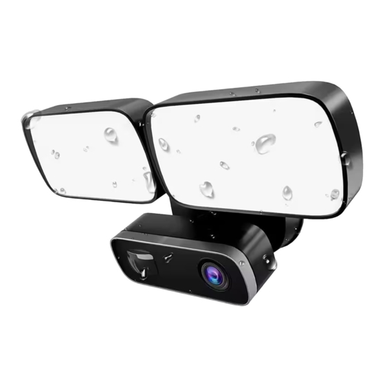
1.Packing List Open the package, then make sure the floodlight cam(device) is intact, and with all the below accessories. Smart Floodlight Cam Installation Manual Please refer to the installation pictures in the App, and read this manual and keep it handy during installation. Hook Hang your Floodlight Cam while connecting the wires. - Page 4 Waterproof rubber gasket Use the waterproof rubber gasket between the base and the floodlight cam Philips big flathead self-drilling screw (4) Use 2 of these to attach the supplied bracket to your on the wall. Plastic Expansion Nails Plug (4) Knock the plastic expansion nails plug into the hole.
- Page 5 2.How it all fits together 4*28 Mounting Wire Plastic bracket Nuts expansion Bracket screws...
- Page 6 Light Adjustment Rubber Knob cover Camera Motion Lock Detector (for lights) Collar...
- Page 7 3.The proper installation height to optimize 3.How installation height to the motion sensor performance optimize the motion sensor WARNING In order to prolong service life of the equipment, please try to install the equipment in a place without rain and high temperature and humidity. Parallel to groud 26 feet (8 Meters)
- Page 8 When mounted at 3 meters off the ground, with the motion detector about 30 degree to the ground, the detect human-sized objects distance up to 8 meters. 9 feet (3 Meters)
- Page 9 Step 1 - Shut power off at the fusebox If you don’t know where your breaker is or how to turn off power to the floodlight circuit, consult with a licensed electrician. Please switch it from [ON] to [OFF] WARNING: Risk of electrical shock WARNING Disconnect power at the circuit breaker before installing.
- Page 10 Step 2 - Remove the mounting bracket Use a screwdriver handle to unscrew the nut. Remove the mounting bracket.
- Page 11 Step 3- Install the bracket waterproof rubber gasket Attach the waterproof rubber gasket into the mounting bracket, press the 6 holes to fix it.
- Page 12 Step 4- To determine the location First, determine the height of the chassis, and then use the pen to draw the position of the screw hole, make a mark.
- Page 13 Step 5 - Choose a proper place for drilling Before drilling, ensure that the hole does not impinge on pipe work, cables or other building services. Knock the plastic expansion nail plug into the hole.
- Page 14 Step 6 - Fix base Carefully push all the wires through the large opening in the bracket. Tighten the screw and fix the base. Pay attention to the horizontal position on the top.
- Page 15 Step 7- Connect the power wire Connect power wire to terminals Black(Hot) and White( Neutral) Brown(Live) White(Neutral) Ternimals(G) If you don’t know which is neutral or hot wire coming out of the junction box, consult with a licensed electrician. Align the mounting posts with the holes on Floodlight Cam and press together, securing the screw cap nuts with the screwdriver.
-
Page 16: Step 8 - Mounting Bracket
Step 8 - Mounting bracket Tighten the screws with philips bit. Put the waterproof rubber cap on the screw hole. - Page 17 Step 9 - Adjust the Angle of the light and camera Loosen or tighten the screw to adjust the light angle Loosen or tighten the screw to adjust the camera angle Do not remove your led light part or camera part from the ball socket on the base.
-
Page 18: Step 11 - App Setup
Step 10 - Restore power at the breaker After restoring power, the lights will turn on and your Floodlight Cam will begin speaking to you to let you know it is in setup mode. Please switch it from [OFF] to [ON] Step 11 - App setup Open the App, follow the user manual to connect Floodlight Cam to your WiFi network. - Page 19 Connect Floodlight Cam to Your APP...
- Page 20 1.Preparation Please prepare the below stuff before you use it. One smartphone or tablet PC(Mac or Windows PC is not acceptable) with IOS 10.0 or Android 4.4 system(higher version system is acceptable) Android phone iPad iPhone Wi-Fi Router Device can only connect to 2.4Ghz Wi-Fi router. Make sure turn on the DHCP of router, and MAC address should be off.
- Page 21 Green LED indicator status: No power or WiFi connected Device is starting Slow blink Fast blink Waiting connect to WiFi WiFi disconnected Micro SD card user caution To ensure SD card video recording works steady, we recommend Class 10 or above version high speed Micro SD card. To make sure the device works normally, please format the SD card before the first time use.
-
Page 24: Configure Device
3.Configure Device Open the App AT&T 11:57 AM My Device Click " " 2.4G Wi-Fi Make sure your smart phone is connected to WiFi router before the configuration. AT&T 11:57 AM My Device First Add Click "First Add" Manual Add... - Page 25 AT&T 11:57 AM Device Name Name the device What would you like to name the device? BackYard Front Door Side Side Customize... AT&T 11:57 AM Scan QR Code Light Scan the QR code on the back housing Scan the QR code on the back housing. Option 1: Cannot scan QR code? Option 2:...
- Page 26 WARNING AT&T 11:57 AM Input WiFi Password Cancel Don't use the Chinese or special Test1 WiFi SSID: symbol to name the WiFi. Please input WiFi password WiFi Password: Don't use the Chinese or special Next symbol as the password of WiFi. Input the right password of the WiFi Please put your smart phone or AT&T...
- Page 27 Wait for about 60 seconds, the configuration will be done. (After the configuration is sucessful, AT&T 11:57 AM the green LED indicator will be off in Configure Device about 60 seconds.) If configuration failed 100% Please make sure input right password( check the capital&small letter,blank) Please keep the distance between the device and the WiFi router within 5m.
-
Page 28: Watch Video
4.Watch Video AT&T 11:57 AM BackYand 2018/01/01 08:30 AUTO Make an emergency call Siren(Activate the 110 Siren decibel siren) Light switch To view the photos and Storage videos AT&T 11:57 AM Return BackYand 2018/01/01 08:30 Ring the bell Listen Full screen LD/HD Switch Recording Snapshot... - Page 29 Tips on WIFI Configuration 1.Make sure the device is powered on. 2.Make sure the device is ready to be configurated. Slow blink 3.Make sure the phone is connected to WiFi,and the volume is the maximum. Please adjust the volume to maximum 4.Make sure using the 2.4GHz , and the router's DHCP is turned on.(If you don't know how to switch from 5Ghz to 2.4Ghz, please consult to the service provider of...
- Page 30 Tips on WIFI Configuration If failed again, please: 1.After the device is powered on, press and hold the " Reset" button for 5 seconds , reset the device, wait for 40 seconds, hear the sound 3 times . 2. Reboot the router . If you USE "Wi-Fi extender"...
- Page 31 For more questions, please refer to FAQ list in Our APP AT&T 11:57 AM My Device Open the App, then click " " AT&T 11:57 AM My Device Feedback Product instructions Click "FAQ" enter FAQ page...
-
Page 32: Fcc Statement
FCC Statement Changes or modifications not expressly approved by the party responsible for compliance could void the user's authority to operate the equipment. This equipment has been tested and found to comply with the limits for a Class B digital device, pursuant to Part 15 of the FCC Rules. These limits are designed to provide reasonable protection against harmful interference in a residential installation. - Page 33 About the User Manual: The user manual is used as a guide. The photos, graphic, charts and illustrations provided in the user Manual are only used to explanation and interpretation, which may be different from specific products, please refer to the real object. The user manual maybe updated because of the products version upgrade or other requirements, if you need the latest version of the user manual, please contact customer service for the latest version of the user manual.
Need help?
Do you have a question about the GFL400 and is the answer not in the manual?
Questions and answers