
Related Manuals for WOBIT SID116


Summary of Contents for WOBIT SID116
- Page 1 User manual SID116 DC motor driver with USB and RS485 – Modbus interfaces P.P.H. WObit E.K.J. Ober s.c. 62-045 Pniewy, Dęborzyce 16 tel. 61 22 27 422, fax. 61 22 27 439 e-mail: wobit@wobit.com.pl www.wobit.com.pl...
-
Page 2: Table Of Contents
Programmable inputs ..........................12 Analog input ............................... 13 Programmable outputs ..........................13 Control interfaces ............................14 Communication interfaces ......................... 15 SID116 – PC software .......................... 16 USB connection with PC ..........................16 Application interface description ....................... 16 Driver configuration ..........................25 Commissioning............................25 Open loop operation (PWM mode) ...................... - Page 3 Based on the information should not be inferred a certain features or suitability for a particular application. This information does not release the user from the obligation of own judgment and verification. P.P.H. WObit E.K.J. Ober s.c. reserves the right to make changes without prior notice. ...
-
Page 4: Safety And Assembly Rules
While mounting it is recommended to keep proper driver position to provide proper heat dissipation. It is recommended mounting with space minimum 50 mm from next device to provide proper air circulation. www.wobit.com.pl User manual SID116 – 09.04.2015r. v.1.0 page 4... -
Page 5: Introduction
2. Introduction Intended use SID116 is a sophisticated DC motor driver which allows to control current, velocity, position and trajectory with symmetrical trapezoidal velocity profile. Driver allows motor control with direct current up to 16 A and voltage up to 30 V and 4Q operation (motor can operate as a drive or as generator depend on current load and rotation direction). -
Page 6: Functions
Thermal and overload protection. 2.2 Functions Main function of SID116 driver is control of drive operation with DC motor driver according to selected regulation mode and control signal. For each operation mode driver has independent memory of 16 settings. Each setting consist in numerical value and type which defines if setting is absolute or relative. - Page 7 Excessive of energy is dissipated on internal resistor or on external in case of higher load. www.wobit.com.pl User manual SID116 – 09.04.2015r. v.1.0 page 7...
-
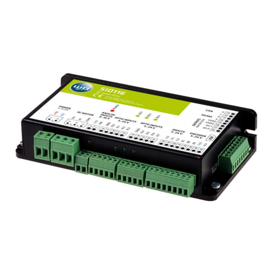
Page 8: Device Description
3. Device description Connectors and indicators arrangement Picture. 4. SID116 indicators description www.wobit.com.pl User manual SID116 – 09.04.2015r. v.1.0 page 8... -
Page 9: Power Supply
Do not clench +5 V outputs with ground (GND) neither with power supply. It can cause damage of a driver. Please avoid leading cables with +5 V signal in close to other signal which can generate noises. www.wobit.com.pl User manual SID116 – 09.04.2015r. v.1.0 page 9... -
Page 10: Motor And Braking Resistor
CAUTION! After connection of external braking resistor please properly set power and resistance of resistor and driver power supply at SID116 – PC application. Lack of settings or entering wrong settings can cause damage of a drive. It is recommended to use a ferrite bead on motor cables to eliminate noises from commutator. -
Page 11: Incremental Encoder
Incremental encoder At velocity and position adjustment modes it is required to connect an encoder to the driver. SID116 allows connection of incremental encoder with operating voltage 5..24 V. Encoders with supply 5 V can be supplied directly from +5 V (25) output. Maximal output current efficiency is 150 mA. -
Page 12: Programmable Inputs
None opto insulation, ground common with driver power supply ground High state: 24 V (min 2 V, max. 26 V) Low state: < 2 V Picture. 10. Inputs without insulation (I1.0 - I1.2) www.wobit.com.pl User manual SID116 – 09.04.2015r. v.1.0 page 12... -
Page 13: Analog Input
Opto insulation Constant load max 2 A at 24 V for channel Voltage range 12..24 V Build-in protection diode for inductive load Picture. 12. Programmable output with opto insulation www.wobit.com.pl User manual SID116 – 09.04.2015r. v.1.0 page 13... -
Page 14: Control Interfaces
3.8 Control interfaces Driver allows connection of external interfaces using I0.6 (16) and I0.7 (17) fast inputs. Inputs operate as interface are not filtrated. Each pulse generated on input is counted by internal counting system and after counting is transmitted by control signal. Examples of interface signal configurations are presented below. Parameters: ... -
Page 15: Communication Interfaces
3.9 Communication interfaces Driver allows communication at USB standard for driver parameters configuration by SID-PC application. SID116 is detected as standard HID type device, system drivers for communication are included in operation system. SID is additionally equipped with MODBUS – RTU protocol on RS485 bus. Driver is operating as SLAVE device. -
Page 16: Sid116 - Pc Software
4. SID116 – PC software USB connection with PC Driver configuration and programming is made using SID116-PC application. Driver should be connected with PC using USB cable A – B mini type. After connection to computer please turn on driver power supply and run SID116 –... - Page 17 Picture. 18. Advanced settings panel www.wobit.com.pl User manual SID116 – 09.04.2015r. v.1.0 page 17...
- Page 18 Master encoder – tracking operation, tracking external signal of encoder. AB pulse - pulse control mode. Binary inputs – control using digital inputs with binary counted value to setting index. www.wobit.com.pl User manual SID116 – 09.04.2015r. v.1.0 page 18...
- Page 19 Signal fields allows to display values of selected signals. Parallel inputs field indicates index inidcated by index inputs at parallel mode. Binary inputs field indicates by index inputs at binary mode. 4.2.2 Advanced settings. www.wobit.com.pl User manual SID116 – 09.04.2015r. v.1.0 page 19...
- Page 20 Maximal current while homing in mA Homing velocity Homing velocity in rpm Homing position Position after homing – drive after homing will execute movement to set position (only positive values) 02. Regulator parameters www.wobit.com.pl User manual SID116 – 09.04.2015r. v.1.0 page 20...
- Page 21 4.2.3 I/O configuration. All SID116 driver I/O are mappable i.e. for any I/O there is a possibility to ascribe any signal from allowable signal range. Moreover fot each I/O can be independently configured its polarity. I/O configuration window is avaliable at application menu ->...
- Page 22 HIGH – active signal state corresponds to high state on output LOW – active signal state corresponds to low state on output 12 – Configuration of signals assigned to output www.wobit.com.pl User manual SID116 – 09.04.2015r. v.1.0 page 22...
- Page 23 SPEED_OK – set velocity achieved MAX_LIM – active positive limit switch MIN_LIM – active negative limit switch COMMUNICATION – Signalization of receiving Modbus frame BREAK – Control signal of mechanic brake www.wobit.com.pl User manual SID116 – 09.04.2015r. v.1.0 page 23...
- Page 24 Third window column allows to select if error will cause emergency mode. First four erros are a critical erros and can’t be deactivated. Picture. 21. Errors handling window www.wobit.com.pl User manual SID116 – 09.04.2015r. v.1.0 page 24...
-
Page 25: Driver Configuration
Software update. Before commissioning it is recommended to download the latest software from www.wobit.com.pl. At catalogue with software is placed SID116–PC application used for driver configuration and current version of driver firmware with FirmwareUpdater.exe program for its update. Before commissioning please update firmware according to manual included in catalogue. - Page 26 IX Last configuration stage is configuration of braking resistor. Please execute it according to description at 5.7 chapter. In case of drives with low inertia/power build-in, internal resistor of SID116 is enough. At driver is build-in 10 Ω resistor with power 10 W.
- Page 27 XV Each pressing of R6 button should increase PWM (1) signal value by 100. Mentioned above activity should be repeated until motor will start to rotate. Please pay attention to current driver current consumption (2). www.wobit.com.pl User manual SID116 – 09.04.2015r. v.1.0 page 27...
- Page 28 XVI If while configuration occurred errors or drive operates incorrectly e.g. it heats, go to 5.8 chapter. If motor operates correctly it can be used in Open Loop mode. For activation of regulation modes it is necessary regulator adjusting 5.3. www.wobit.com.pl User manual SID116 – 09.04.2015r. v.1.0 page 28...
-
Page 29: Open Loop Operation (Pwm Mode)
Furthermore at open loop mode current limit is active. If motor current will exceed rated current set at application settings driver will limit it to safe value. Drive can signalize overloads which is defined at error handling window. Regulator adjusting. 5.3.1 Regulator structure. www.wobit.com.pl User manual SID116 – 09.04.2015r. v.1.0 page 29... - Page 30 Regulators are connected to each other creating a sequence. This means that input of slave regulator is controlled by output of master regulator. SID116 driver regulator consist of current, velocity and position regulator. Position regulator input is set position. Position regulator output is connected to velocity regulator.
-
Page 31: Current Regulation
(7). At advanced settings tab please enter rated voltage lower than current voltage. It will cause limiting of voltage transmitted to a motor. After configuration settings should be saved using button placed at main application window. In other case voltage decline will restore previous driver settings. www.wobit.com.pl User manual SID116 – 09.04.2015r. v.1.0 page 31... -
Page 32: Velocity Regulation
Position regulation mode allows to control driver set position. To activate this mode please select Position Regulator and press „Activate mode” button (1). All values at this mode are in steps which correspond to encoder www.wobit.com.pl User manual SID116 – 09.04.2015r. v.1.0 page 32... - Page 33 Velocity profile allows to define maximal velocity and acceleration values for velocity changes. To activate this mode please select „ON” option (8) and enter profile parameters: maximal velocity (9) and acceleration (10). www.wobit.com.pl User manual SID116 – 09.04.2015r. v.1.0 page 33...
-
Page 34: Dynamic Braking (Braking Resistor)
5.7.1 Dynamic braking function. SID116 is a 4Q driver. It allows motor control as well as normal operation as at generator mode. At normal mode motor charge energy from power supply and exchange into mechanical energy driving mechanical system. At generator mode motor is drive by mechanical system e.g. - Page 35 5.7.2 Braking resistor. Parameters selection. Driver has build-in cement resistor with resistance 10 Ω and rated power 10 W. SID116-PC software provides configuration of power and resistance of braking resistor. Picture. 29. Braking resistor Default parameters are consonant with settings of internal resistor.
-
Page 36: Driver Error Handling
Driver error handling. 5.8.1 Errors description Table 6. SID116 driver allows the user access to following error signals Signal Description Type Voltage supply <10 V Voltage supply below minimal voltage Voltage supply >36 V Voltage supply above maximal level Critical Exceeding of allowable operating System overheating >105°C... - Page 37 Overregulation of current regulator Please decrease current regulator settings regulator Drive starts vibrate or oscillate while Overregulation of position or velocity Please check and if necessary decrease position operation regulator or velocity regulator settings www.wobit.com.pl User manual SID116 – 09.04.2015r. v.1.0 page 37...
-
Page 38: Modbus Communication
Stop bit: 1, Parity: none Timeout: 750µs (max interval between next bytes in frame) Communication description, list of user registers and way of drive control by MODBUS-RTU is available at „SID116_protokol_MODBUS.pdf”documentation. www.wobit.com.pl User manual SID116 – 09.04.2015r. v.1.0 page 38... -
Page 39: Record Of Changes
7. Record of changes Table 8. Record of changes Version Firmware PC program 1.00 - first version - first version www.wobit.com.pl User manual SID116 – 09.04.2015r. v.1.0 page 39... -
Page 40: Technical Parameters
RS485: Communication protocol: MODBUS - RTU SLAVE Communication USB: 1.1, 2.0 (HID): Parameters configuration Operation temperature range 5..50 Weight 280 g (without radiator) Housing 139x80x30 mm (without radiator), mounting on DIN rail Degree of protection IP20 www.wobit.com.pl User manual SID116 – 09.04.2015r. v.1.0 page 40...
Need help?
Do you have a question about the SID116 and is the answer not in the manual?
Questions and answers