Advertisement
Available languages
Available languages
Quick Links
Advertisement

Subscribe to Our Youtube Channel
Summary of Contents for Steren K-920
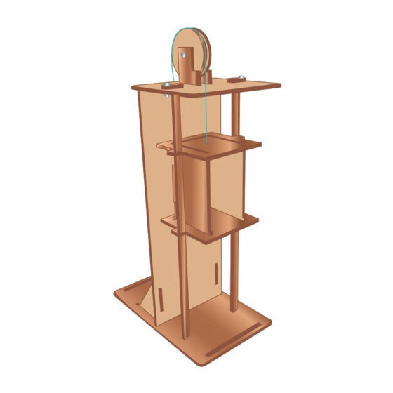
- Page 1 K-920 KIT ELEVADOR ELECTRÓNICO 0618A MANUAL DE INSTRUCCIONES V0.0...
- Page 2 IMPORTANTE Antes de utilizar su nuevo producto Steren, lea este manual para evitar cualquier mal funcionamiento. La información que se muestra en este manual sirve únicamente como referencia sobre el producto. Debido a actualizaciones pueden existir diferencias. Por favor, consulte nuestra página web www.steren.com para obtener la versión más reciente del manual.
-
Page 3: Table Of Contents
CONTENIDO Maneje las piezas con cuidado, pueden PIEZAS DEL CHASIS romperse facilmente. Cant. Cant. Cant. 1 pza. 1 pza. 2 pzas. Cant. Cant. Cant. 2 pzas. 2 pzas. 1 pza. Guias 4.2 cm de diametro Cant. Cant. Cant. 2 pzas. 2 pzas. -
Page 4: Cant
Tuerca de seguridad Cable dupont Cant. Cant. Cant. Cant. 2 pzas. 1 pza. 1 pza. 8 pzas. Motorreductor Tornillo grande Tornillo chico Hilo de nylon Cant. Cant. Cant. Cant. 6 pzas. 1 pza. 1 pza. 3 pzas. PIEZAS DE LA TARJETA Resistencia 560 Header Q1 - Q4... - Page 5 ENSAMBLAJE Asegúrese de colocar las piezas correctas Comience a ensamblar desde la base. antes de aplicar pegamento. Coloque pegamento Coloque pegamento Pase las piezas G por debajo de la pieza A con cuidado.
- Page 6 Arme la cabina del elevador Coloque pegamento...
- Page 7 Tenga cuidado de no dañar las piezas G...
- Page 8 Coloque la pieza B atrás de la cabina. Utilice las piezas J como soporte Coloque pegamento...
- Page 9 Coloque la pieza M para asegurar la pieza B y las piezas G...
- Page 10 Coloque las piezas sobre M y G. Utilice tornillos U para asegurarlos junto con tuercas S Coloque pegamento Utilice pinzas y desarmador para apretar tornillos y tuercas.
- Page 11 ARMADO DE POLEAS Utilice 2 piezas L y coloque en medio la pieza I. En ambas orillas coloque piezas K, asegure todas las piezas con un tornillo T y tuerca S Coloque pegamento No apriete mucho la tuerca porque la polea debe girar para que baje y suba la cabina del elevador Utilice pinzas y desarmador...
- Page 12 Tome la pieza O, pase el hilo V y haga un nudo asegurando la pieza O, en seguida pase el hilo por el orificio de la cabina y páselo por arriba de la polea hasta llegar a la pieza Ñ y amarrelo al agujero.
- Page 13 ARMADO DE PCB Ponga atención a la polaridad de los cables 11A: Tome el cable dupont (R), corte un extremo y pele el cable, suelde en las terminales del motor, cada una en un extremo. Ñ 11C: Coloque las piezas N y Ñ 11B: Inserte las piezas H como se muestra en la imagen, por debajo del chasis, péguelas...
- Page 14 12D: Coloque una batería de 9 V en el orificio y conéctela al broche. 12C: Suelde los cables del broche de pila o pieza J1, como se muestra en la imagen. 12A: Coloque la placa con los componentes Ponga atencion a la previamente soldados, atornille por sus 4 polaridad de los cables extremos con tornillos U y asegúrelos...
- Page 16 K-920 ELECTRONIC ELEVATOR KIT 0618A INSTRUCTION MANUAL V0.0...
- Page 17 IMPORTANT Before using your new Steren product, read this manual to avoid any malfunc- tion. The information shown in this manual serves only as a reference for the product. Due to updates there may be differences. Please check our website www.steren.com for the most recent version of the manual.
- Page 18 CONTENT Handle the parts with care, you can PARTS OF THE CHASSIS break easily Cant. Cant. Cant. 1 pza. 1 pza. 2 pzas. Cant. Cant. Cant. 2 pzas. 2 pzas. 1 pza. Guides 4.2 cm in diameter Cant. Cant. Cant. 2 pzas.
- Page 19 Safety nut Dupont cable Cant. Cant. Cant. Cant. 2 pzas. 1 pza. 1 pza. 8 pzas. Gearmotor Large screw Small screw Nylon thread Cant. Cant. Cant. Cant. 6 pzas. 1 pza. 1 pza. 3 pzas. CARD PARTS Resistance 560 Header Q1 - Q4 Transistor 2N 2222 Stack brooch...
- Page 20 ASSEMBLY Be sure to place the correct parts Start assembling from the base. before applying glue. Place glue Place glue Pass the pieces G under piece carefully.
- Page 21 Assemble the elevator cabin Place glue...
- Page 22 Be careful not to damage the G pieces...
- Page 23 Place part B behind the cab. Use the J pieces as support Place glue...
- Page 24 Place part M to secure part B and parts G...
- Page 25 Place part M to secure part B and parts G Place glue Use pliers and screwdriver to tighten screws and nuts.
- Page 26 ASSEMBLY OF PULLEYS Use 2 pieces L and place the piece I in the middle. On both sides place pieces K, secure all the pieces with a screw T and nut S Place glue Do not tighten the nut too much because the pulley must turn to lower and raise the cabin of the elevator...
- Page 27 Take piece O, pass thread V and tie a knot securing piece O, then pass the thread through the bore of the booth and pass it up from the pulley until you reach the Ñ part and tie it to the hole.
- Page 28 ARMING OF PCB Pay attention to the polarity of the cables 11A: Take the dupont cable (R), cut one end and Strip the cable, weld on the motor terminals, each one on one end. Ñ 11C: Place the pieces N and Ñ 11B: Insert the parts H As shown in the picture, under the chassis, stick them...
- Page 29 12D: Place one 9 V battery in the hole and connect it to brooch. 12C: Solder the cables of the battery clip or piece J1, as shows in the image. 12A: Place the plate with the components Pay attention to the previously welded, bolt for your 4 polarity of the cables ends with U screws and secure them...
Need help?
Do you have a question about the K-920 and is the answer not in the manual?
Questions and answers