Download Print this page

Advertisement

Quick Links

MODELS
A C , Superheterodyne, High-Picture-Definition, Five-Television-Channel, Receiver
' Three-Band, Electric Tuning, A C , Superheterodyne Broadcast Receiver
Models TRK-12, TRK-120
T R K - 9 , T R K -9 0
H eight.................... 47% in.;
Width . . . . . . . . . . 31 Vi in.; . W eight........ ............... 200 lb.
Shipping W eight.............................................. 2831b.
Model TRK-12:
Chassis KC-4, KK-7, RC-427, RS-83E,
105*125 volts, 60 cycles...................... 420 watts (total)
Chassis KC-4B, KK-7DV RC*427, RS*
83E, 105*125 volts, 50*60 cycles.. . . 420 watts (total)
Model TRK-120:
Chassis KC*4F, KK*7F, RC*427F, RS*
83E, 105*125 volts, 60 cycles........... 420 watts (total)
Chassis KC*4j, KK*7J, RC*427F, RS*
83E, 105*125 volts, 50*60 c y c le s .... 4 2 0 watts (total)
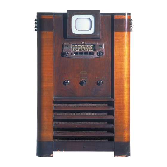
Models TRK*12 and TRK*120 arc console-type, high*
picture-definition, mirror-viewing, five channel. Television
Receivers and thrcc*band broadcast radio receivers enclosed
in handsomely styled modern cabinets. Features of the Tele*
vision
receiver
include:
(humidity-resisting) r*f and i*f transformer forms: black and
white pictures; single station selector switch: temperature com*
pensated condensers; iron core i-f and r*f tuning; double
RCA M O R
P p S I O M OF RADIO C O R P O R A T lO h aP ^ AM ERICA, . C A fM ŚIŃ N . H , l ^ A .
TRK-9, TRK-12, TRK-90 and TRK-120
General Specifications
D epth..............
24% jin.
Chassis Numbers and Power Supply Ratings
General
Twelvc*inch
Kinescope;
Styrol
and
Models TRK-9, TRK-90
T R K - 1 2 , T R K - 1 2 0
H e i g h t . . . . . . . . . . 4 0 % in.;
W id th ............. ..
34% in.;
Shipping W eight............................................... 2751b.
Model TRK-9:
Chassis KC-4A, KK-7 A, RC-427A, RS*
83E, 105*125 volts, 60 cycles........... 420 watts (total)
Chassis KC-4C, KK-7E, RC*427A, RS*
83E, 105*125 volts, 50*60 c y c le s .... 420 watts (total)
Model TRK-90:
Chassis KC-4H, KK-7H, RC-427G, RS*
83E, 105*125 volts, 60 cycles........... 420 watts (total)
Description
safety switch protection; safety*glass viewing shield; and extra
large viewing mirror for wide angle viewing.
Models TRK-9 and TRK-90 are direct viewing, high*
picture-definition, console-type, five channel, Television Re*
ccivers and three-band broadcast radio receivers in deluxe up*
right modern cabinets. Television features of these receivers
arc the same as for the TRK-12 and TRK-120, except that a
nine-inch Kinescope is used.
PAGE 2 5 1 - C
D e p th ...............* . . 1 9 % in.
W e ig h t.................
198 lb.

Advertisement

loading
Need help?

Need help?

Do you have a question about the Victor TRK-9 and is the answer not in the manual?

Questions and answers

Summary of Contents for RCA Victor TRK-9

  • Page 1 Kinescope is used. RCA M O R P p S I O M OF RADIO C O R P O R A T lO h aP ^ AM ERICA, . C A fM ŚIŃ N . H , l ^ A .
  • Page 2: Electrical Specifications

    In KC-4F, KC-4J (TRK-120) and KC-4H (TRK-90) Video Chassis: ( 1) RCA-6AC7/1852........ 1st Det. (12) RCA-6SK7......1st Sound I.F; ( 2) R CA -6J5....... Oscillator (13) RCA-6AB7/1853....
  • Page 3: Operation

    People not so equipped should be kept away while handling Kinescopes. All RCA Kinescopes arc shipped in special cartons and Keep Kinescope away from the body while handling. should always be left in the cartons-until ready for installa-...
  • Page 4 PAGE 2 5 4 - C TRK9, TRK90, TRKI2, TRKI20 D A T A SERVICE Kinescope Installation (TRK-9, TRK-90). edges on the Kinescope screen. Before rotating the Kine' scope, the screws holding the yoke mounting block should be 1. Remove back cover of cabinet. loosened, so that the Kinescope neck will not be forced.
  • Page 5 PAGE 2 5 S - C...
  • Page 6 Service Hints: Poor Horizontal Distribution of the picture elements may be due to a 6L6 tube. RCA-6L6 tubes of known recent manufacture, are*the only tubes recommended for the Hori­ zontal sweep output circuit. By careful scrutiny, these tubes can be identified by the three “ rings" or sections welded to*...
  • Page 7: Antenna Installation

    For further information on antennas and antenna installa' In mounting any antenna, care must be taken to keep the tion see RCA Booklet entitled: “ Practical Television by antenna rods or pickup wires proper at least ł/» wave length RCA,” and also the specific instructions accompanying the (at least 6 feet) away from other antennas, metal roofs and RCA Television Antenna.
  • Page 8 PAGE 2 S 8 -C...
  • Page 9 PAGE 2 5 9 - C...
  • Page 12 PAGE 2 6 4 - C TRK9, TRK90, TRKI2, TRKI20 — Television Service Suggestions Some of the possible troubles that may become evident 10. Picture folded back at left-hand side. If the picture is during air-check of Models TR K '9, '12, '90, '120 are listed lapped'over, or folded back on the left'hand side, change the below, together with the most likely causes of each trouble, horizontal damper tube.
  • Page 13 PAGE 2 6 5 - C TRK9, TRK90, TRKI2, TRKI20 Figure 12— Partial Video Chassis W iring T R K -9 and T R K -1 2 W ith Picture A V C . Otherwise same as Figure 13. Television Service Suggestions (Continued) the 5V4-G damper tube can be replaced by a 5Z4.
  • Page 16 A better power supply as the television transmitter, the interference method is to use the RCA Chanalyst U H F Converter: Place will be stationary. Otherwise it will travel up or down on the the input probe on the picture 2nd'detector load resistor picture.
  • Page 17 r ^ ^ / U A r — V . PROTECTIVE SLEEVE (D O NOT REMOVE FROM TUBE) CONICAL M ETALLIC SHIELD. KINESCOPE ( 1 8 0 3 * 4 ) SLOT FOR WING NUT O U T E R S H IE L D YOKE CLANSP (WING N U T *1 0 -3 2 ( S t o c k * s a a ©...
  • Page 18 (1 ) A shielded yoke (RCA Stock No. 9857N). This has ceiver. A test oscillator can be coupled to the receiver input a metal pigtail at plug end of cable for grounding while a television program is being received.
  • Page 19 PAGE 2 7 2 - C TRK9, TRK90, TRKI2, TRKI20 ¥ DISCONNECT BOTH OF ■ th e s e L E A D S , ANO CONNECT THe TERMINAL OF C 114 TO GROUND B E F O R E ' MAKIN6 ANY VOLTAGE MEASUREMENTS E IT H E R ON T H IS...
  • Page 20 R 0 4 2 7 and R 0 4 2 7 A only: R C A 6 U 5 ..... Magic Eye ( 6 ) RGA-6R7..... 2nd-Det., A.F., A.V.C., and Muting (1 1) RCA'5U4G (In RS'83E S P U ) .. . Full'W ave Rectifier J Two Mazda No. 44, 6.3 volts, .25 amp.
  • Page 21 PAGE 2 7 4 - C TRK9, TRK90, TRKI2, TRKI20 Electric Tuning Mechanism W hen a station button is pushed in, it completes the 24- T he brass selector disc is fastened to the rear shaft of the volt circuit through the corresponding station*setting contact tuning condenser by means of two set-screws.
  • Page 22 PAGE 2 7 5 - C...
  • Page 23 PAGE 2 7 6 - C TWO, TRK90, TRKI2, TRKI20 "1 ’? w > g £ « 42 ;> ■ ffj w 42 o § <o £: e 3"^ p l s p J! « +! ° 8 ^ $> <...
  • Page 24 PAGE m - c TRK9, TRK90, TRKI2, TRKI20 Fidelity Switch (S 110-V. Supply Switch Audio Osc. -f B Dial for Tele. Position Amp. Amp. Lamps** Supply Chassis* No. 1 (Counter­ Min. Highs Victrola — clockwise) Max. Highs No. 2 Victrola —...
  • Page 25: Alignment Procedure

    278-C PAGE TRK9, TRK90, TRKI2, TRKI20 A lignm ent Procedure (RADIO CHASSIS) Figure 29— A t Right— Tube and Trim m er Locations Cathode-Ray Alignment is the preferable method. Connections for the oscilloscope are shown in the chassis drawing. O utput M eter Alignment. — If this method is , used, connect the meter across the voice coil, and tu rn the receiver volume control to maximum.
  • Page 26 ________________________ PAGE 2 7 9 ~ c TRK9, TRK90, TRKI2, TRKI20 Miscellaneous Data for Radio Chassis Feedback Switch (S8 and S9) Precautionary Lead Dress (TRK-9 and TRK-12 only) (1 ) All A 'C leads should be twisted together and dressed away from parts in chassis to prevent hum pickup.
  • Page 27: Replacement Parts

    PAGE 2 S O -C TRK9, TRK90, TRKI2, TRKI20 REPLACEMENT PARTS jnshl on genuine fictory-U.ted pits, which ait ffd ily Identified and may bt purchased from authorized dtalan. STOCK DESCRIPTION STOCK DESCRIPTION TE LEV ISIO N CHASSIS ASSEM BLIES 33206 Control—...
  • Page 28 PAGE 2 8 1 - C Replacement Parts (Continued) TRK9, TRK90, TRKI2y IRK 120 STOCK DESCR IPTIO N J STOCK DESCRIPTIO N Socket— 4-contact female socket for Kinescope 32096 Disc— Friction disc and pinion g e a r ...... deflecting yoke ( X I ) ......... 32091 Drive—...
  • Page 29 32937 Knob— Focus control- knob........range" decal..........‘....33244 Plug— 2-prong male connector for A.C. power 35392 Decalcomania— "RCA Victor" decal..... cord ( X 2 2 )..............35892 Decalcomania— "Station selector” decal..33166 Plug— 2-prong male plug for Kinescope grid- 35895 D ec alcomania—...

This manual is also suitable for:

Victor trk-12Victor trk-90Victor trk-120