
Summary of Contents for Zombie REC mComp
- Page 1 μCOMP Diode Compressor (r1.1) Assembly Guide www.zombierecaudio.com info@zombierec.com Last Updated: March 13, 2022 All content Copyright ©2022 Zombie REC. Specifications are subject to change without notice.
- Page 2 Disclaimer Zombie REC. is not liable for any damage, harm or loss of any kind resulting from the assembly and/or use of this kit. Improper soldering and handling of electricity can cause serious injury and damage to your property. Also, keep all contents away from children. Follow the guide, build carefully and pay attention when using the necessary tools.
- Page 3 Kapton tape or clear office tape • Scissors to cut the tape • • Optional but recommended: Means to ground yourself, like a properly connected ESD wristband All content Copyright ©2022 Zombie REC. Specifications are subject to change without notice.
-
Page 4: Kit Contents
1x 50k / 1x 100k / 1x 220k PCB (not shown in picture) This build is a bit more complex and you should plan enough time to build it. All content Copyright ©2022 Zombie REC. Specifications are subject to change without notice. - Page 5 Cut some tape as shown below, it should be long enough to be applied by using both of your hands. Use the scissor to cut it to prevent it from sticking to your finger prematurely. Carefully hold the All content Copyright ©2022 Zombie REC. Specifications are subject to change without notice.
- Page 6 SMD part with the tweezers bottom up on the tape so that it’s single foot hangs outside (the bottom is where the legs are flush): All content Copyright ©2022 Zombie REC. Specifications are subject to change without notice.
- Page 7 Make sure that the legs are vertically facing the PCB surface and not away from it: All content Copyright ©2022 Zombie REC. Specifications are subject to change without notice.
- Page 8 Now solder the pin by gently pushing the tip of the solder iron on the PCB and the pin and apply some solder: Remove the tape and solder the remaining two pins the same way: All content Copyright ©2022 Zombie REC. Specifications are subject to change without notice.
- Page 9 There are 3x 47pF caps to solder: C5, C12, C13 (red) and 6x 100nF: C1, C2, C7, C8, C10, C11 (blue): We’ll take a closer look now how to properly solder these. All content Copyright ©2022 Zombie REC. Specifications are subject to change without notice.
- Page 10 When you insert them, make sure to firmly push down between their legs to bend them as close and tight to the PCB as possible: All content Copyright ©2022 Zombie REC. Specifications are subject to change without notice.
- Page 11 «overhangs» the hole onto the PCB and locks the part in place that way: Then solder the first lead and repeat the process for all the second leads: All content Copyright ©2022 Zombie REC. Specifications are subject to change without notice.
- Page 12 The pots are conveniently held in place by their leads, but in case its a bit loose, just hold them in place with some tape. Now solder them. Since the stand-offs are long enough, its not necessary to trim their excess leads. All content Copyright ©2022 Zombie REC. Specifications are subject to change without notice.
-
Page 13: Step 4 - 4 Pin Header
We’ll solder the 4 pin header next, as it is most convenient to do it now: For this, use the tape again to hold it into place for soldering: All content Copyright ©2022 Zombie REC. Specifications are subject to change without notice. - Page 14 Flip it over and solder away. If the tape is in the way, solder the easy accessible pins first then remove the tape and do the rest: All content Copyright ©2022 Zombie REC. Specifications are subject to change without notice.
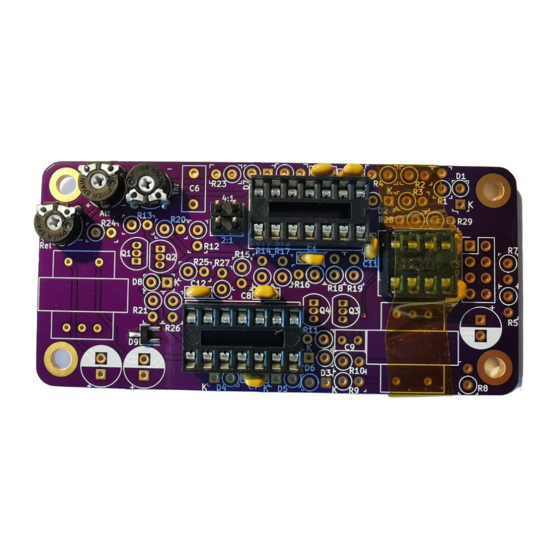
- Page 15 Step 5 – IC Sockets We also do the sockets right away because it’s most convenient to do it now: Start with the 14 pin socket at the bottom. All content Copyright ©2022 Zombie REC. Specifications are subject to change without notice.
- Page 16 While doing so, make also sure that the socket is flush on the PCB: Then flip it over and start soldering. You can remove the tape after soldering at least 4 pins, then finish the rest. All content Copyright ©2022 Zombie REC. Specifications are subject to change without notice.
- Page 17 Then continue with the upper 14 pin socket: And finish with the 8 pin socket: All content Copyright ©2022 Zombie REC. Specifications are subject to change without notice.
- Page 18 After inserting them. Proceed to secure and solder them the same way we did it with the ceramic capacitors before. Go back and check out step 2 again if necessary. All content Copyright ©2022 Zombie REC. Specifications are subject to change without notice.
- Page 19 All content Copyright ©2022 Zombie REC. Specifications are subject to change without notice.
- Page 20 Continue with the remaining 5 diodes. Insert the first diode into D8, and follow up with D3/D5 and D4/D6. Solder them again as shown previously. All content Copyright ©2022 Zombie REC. Specifications are subject to change without notice.
- Page 21 We’ll start with the PNP pair. They are marked with 2N3906: They are placed into Q1 and Q2 on the left. Only populate Q1 for now: All content Copyright ©2022 Zombie REC. Specifications are subject to change without notice.
- Page 22 Insert the transistor into Q1 (check orientation), hold it with your index finger and flip the board around. All content Copyright ©2022 Zombie REC. Specifications are subject to change without notice.
- Page 23 Now bend each lead on the outside in reversed directions from eachother, away from the center. Then let your index finger go: Cut off the lead in the same way you did all the leads up to now: All content Copyright ©2022 Zombie REC. Specifications are subject to change without notice.
- Page 24 Continue with Q3 and Q4. Well use the remaining two NPN here. They are marked with BC550: All content Copyright ©2022 Zombie REC. Specifications are subject to change without notice.
- Page 25 Well use the remaining two NPN here. They are marked with BC550: Solder them the same way as previously shown. Double check the orientations again. The flat surface should correspond with the marking on the PCB. All content Copyright ©2022 Zombie REC. Specifications are subject to change without notice.
- Page 26 Step 8 – Resistors Finally we get to the resistors. We’ll start from right to left as follows (skip R5 and R7 for now): All content Copyright ©2022 Zombie REC. Specifications are subject to change without notice.
- Page 27 Like we did with the diodes before, bend the lead at one side of the resistor and solder them using the exact same technique as before: R8 (bottom): 47k R1, R2, R3 (top): 10k All content Copyright ©2022 Zombie REC. Specifications are subject to change without notice.
- Page 28 R4: 4.99k R28: 470R R29: 1k All content Copyright ©2022 Zombie REC. Specifications are subject to change without notice.
- Page 29 Next up: R9, R10 (bottom): 47k R11: 510R All content Copyright ©2022 Zombie REC. Specifications are subject to change without notice.
- Page 30 R22 (top): 470R R23: 100R Now the center section: All content Copyright ©2022 Zombie REC. Specifications are subject to change without notice.
- Page 31 R16, R17, R18: 10k R19: 2k R14: 47k R15: 470R All content Copyright ©2022 Zombie REC. Specifications are subject to change without notice.
- Page 32 R27: 13.3k R25: 6.65k And finally: All content Copyright ©2022 Zombie REC. Specifications are subject to change without notice.
- Page 33 R12, R20, R24: 10k R13: 61.9k R21: 47k R26: 13.3k All content Copyright ©2022 Zombie REC. Specifications are subject to change without notice.
- Page 34 Solder these the same way we did with all other leaded components up to this point. Populate C6 (top) with the larger 1uF cap and C9 (bottom) with the smaller 1500pF cap: All content Copyright ©2022 Zombie REC. Specifications are subject to change without notice.
- Page 35 While the two transformers are not exactly through hole components, they still can be soldered to keep them in a rock solid position. When done correctly, there will be no wobble at all. Start off with the one in the bottom right: All content Copyright ©2022 Zombie REC. Specifications are subject to change without notice.
- Page 36 Be careful when inserting the wires. Use tweezers to help move the wires into the holes. Make sure the transformer is flush with the PCB and that it does not move when you work on it: All content Copyright ©2022 Zombie REC. Specifications are subject to change without notice.
- Page 37 Prior to soldering, trim excess wires to the same length of the other components. Now repeat with the other transformer: All content Copyright ©2022 Zombie REC. Specifications are subject to change without notice.
- Page 38 Again trim the wires to a suitable length before soldering (shown below are the wires before trimming). All content Copyright ©2022 Zombie REC. Specifications are subject to change without notice.
-
Page 39: Step 11 - Electrolytic Capacitors
Time to solder the special audio grade elcos. Repeat the same lead soldering technique as before: These capacitors are polarized, align the gold marking on the cap with the white marking on the PCB: All content Copyright ©2022 Zombie REC. Specifications are subject to change without notice. - Page 40 Time to wrap up the build. Lets finish it off by soldering the pin header first. Make sure that the long side of the header is pointing down: All content Copyright ©2022 Zombie REC. Specifications are subject to change without notice.
- Page 41 Again use tape to hold the header firmly in place. After soldering one pin, you should be able to remove the tape and solder the rest. Now solder the last two remaining resistors R5 and R7: Start with R7, 220k: and finally R5, 47k: All content Copyright ©2022 Zombie REC. Specifications are subject to change without notice.
- Page 42 (and PCB). Also insert the jumper on the left into the desired ratio position (2:1 or 4:1). Alternatively you can bypass the GR circuit with leaving the jumper out, but more on that in a bit: All content Copyright ©2022 Zombie REC. Specifications are subject to change without notice.
-
Page 43: Step 14 - Final Check
Note that there will still occur some constant gain reduction in this setting, depending on the amplitude of the signal. Please note: The module takes about 5-10 minutes to reach thermal equilibrium. All content Copyright ©2022 Zombie REC. Specifications are subject to change without notice. - Page 44 Thanks and have fun! If you have any questions, don’t hesitate to contact us on info@zombierec.com! All content Copyright ©2022 Zombie REC. Specifications are subject to change without notice.