Table of Contents
Advertisement
Quick Links
Advertisement
Table of Contents

Summary of Contents for SKETCHNBUILD SNB-12A
- Page 1 SKETCHNBUILD MACHINERY...
-
Page 2: Table Of Contents
CONTENTS Ⅰ. Usage and Feature of Structure…………….………………………1 Ⅱ. Technical Parameter..…………………………………...……..……1 Ⅲ. Safety Precautions………………………………………..…..……1 Ⅳ. Machine Installation……………………...…………………..…..…2 4.1 Mounting Safety Cover on Riving Knife…………………………………..……2 4.2 Extension of Table…………………………...………………………………...…..3 4.3 Pressure Utensil …………………………………………………………...……..3 4.4 Workpiece Push Parts…………………………...…………………………...…….4 4.5 Assembly…………………………….……………………………………….……4 4.6. Adjustment after Installation………………………………………………….…..5 Ⅴ. -
Page 3: Ⅰ. Usage And Feature Of Structure
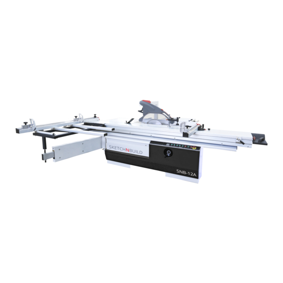
Ⅰ. Usage and Feature of Structure This saw is destined to cut solid wood panel, chipboard, ABS board, PVC board, organic glass board and other board which have the similar structure and hardness. It is the necessary working tool for furniture production and decoration industry. It is made of the body, sliding table, support for sliding table, fixed table, main saw blade, scoring blade, up &... -
Page 4: Ⅳ. Machine Installation
* Stand out of the bounce area of saw blade side and workpiece when operating and do not stand in middle of saw blade. * Remove the loose matters around saw blade before starting the machine. * Cutting shall not be started until the saw blade up to full speed. *... -
Page 5: Extension Of Table
4.1.2 Setting of Riving Knife With respect to safety, the accurate setting of riving knife plays a very important role. The distance between riving knife and toothed ring in cut height area shall be more than 8mm, and the distance in most common use is about 5mm and that of the lower part is 3mm. -
Page 6: Workpiece Push Parts
4.4 Workpiece Push Parts 4.4.1 Push Knife When the wood less than 120mm to be cut, the push knife shall be used to prevent hand from approaching to the saw blade. Push Knife Push Knife Seat 4.4.2 Push Knife Seat When cutting narrow workpiece, lean the workpiece against the rip fence with push knife seat that may be self-made by the operator. -
Page 7: Adjustment After Installation
4.5.2 Installation of Sliding Table Put the sliding table on the position of machine body, align the three set screws with the screw holes and tighten them up. Mount the rear stop plate, check if it is up to the requirement and adjust it otherwise. Before start-up, check each link. -
Page 8: Ⅴ. Operation Of Machine
worktable shall be a little lower about 1/10mm. Setting the moving table, unscrew the lock screws on the four stud bolts, adjust the worktable, tighten up the set screws, then put the rule on the fixed table to be parallel with the moving table, if the surface is sunken, adjust the pressure screw for compensation. -
Page 9: Adjustment Of Saw Blade
5.1 Adjustment of Saw Blade It shall comply with the following requirements by all means: * Don’t mount the cracked or damaged saw blade. * Make a check, the rotary speed of saw blade shall not be too high, and the maximum rotary speed is marked on the saw blade. -
Page 10: Lock Of Moving Table
6,000, which can be reached by moving the V-belt. Shut down the driving, cut off all the power supplies, unscrew the V-belt tension screws on the lift board, and raise it to the left, then the belt position can be adjusted, please refer to the following pictures for operation. -
Page 11: Reaction Of Motor To Overload
5.5.1 Start: Before closing the main power supply switch, the emergency stop switch must be in open condition. Then turn the emergency stop switch to left, and turn on the green button of main saw, hereby the main saw is started. The scoring saw can be started only 5s after main saw starting. -
Page 12: Replacement Of Scoring Saw Blade
Scoring Saw Adjustment Adjust Up & Down Adjust Left & Right Use the handle of scoring saw on right side of panel saw to adjust, one is for adjusting up and down and another is for left and right, turn the handle left and right until aligning to a satisfactory height with the main saw blade. -
Page 13: Ⅵ. Maintenance (Trouble Shooting)
Ⅵ. Maintenance (Trouble Shooting) In trouble shooting process, please operate complying with the following descriptions: Trouble Cause Solution Close the main switch knife “I” Main switch is not started up; Machine can’t be started Interruption occurs in electric Wait for recovery of the electric circuit or some phase;... - Page 14 Trouble Cause Solution Width of the workpiece cut Scale of saw cut width shifts Re-regulate the ruler. Cut a by saw is not corresponding workpiece on parallel check plate with the width regulated on with saw, and measure out the the parallel check plate saw cut width, and then adjust the scale of aluminum ruler to this...
-
Page 15: Ⅶ. Service
Ⅶ. Service Prior to any maintenance for the machine, the power supply shall be cut off to guarantee the safety. Periodic cleaning can prolong the service life, and also is the precondition of perfect cutting effect. Thus the sliding table shall be cleaned at least twice a week according to the service condition. - Page 16 Chapter Fixed Table And Supporting & Adjustment Mechanism Main Saw Auxiliary Saw Machine Body & Turning Arm Bracket Crosscut Guide Plate Straight-cut Guide Plate Double Roller Carriage-Top Carriage Double Roller Carriage-Middle Carriage Double Roller Carriage-Bottom Carriage...
- Page 17 1. Fixed Table And Supporting & Adjustment Mechanism 1. Fixed Table 19. Guide Track 2. Protection Board 20. Bolt 3. Lift Board 21. Pipe Block 4. Connection Board 22. Dust Collection Pipe 5. The Cover of Anti-Dust 23. Guide Track 6.
- Page 18 2. Main Saw 1. Motor Base Spindle 10. Pressure Cushion 2. Motor 11. Main Spindle Sheath 3. Motor Base 12. Bearing 4. Cushion 13. Pressure Cushion 5. Connection Board 14. Main Spindle 6. Adjusting Sheath 15. Adjusting Screw 7. Triangular Belt 16.
- Page 19 3. Auxiliary Saw 16. Inching handle 29. Scoring Saw Spindle 17. Lock nut 30. Bearing 18. Fixed Sheath 31. Scoring Saw Sheath 20. Fixed Base 32. Bearing 21. Feeding Block 33. Sheath 22. Bolt 34. Driving Belt 23. Scorning Saw Turning Base 35.
- Page 20 4. Machine Body & Turning Arm 1. Machine Body 11. Adjusting Spindle 2. Door Cover 12. Hair Brush 3. Bolt 13. Stop Head 4. Angle Adjusting Handle 14. Roll Wheel 5. Board Base 15. Bearing 6. Operation Button 16. Bearing 7.
- Page 21 5. Bracket 1. Plug 14. Pad 2. Holding Plate 15. Stud 3. Handle 16. Ejector Block 4. Pad 17. Bracket 5. Lock Block 18. Shaft 6. Plug 19. Carriage Roller 7. Revolving Shaft Handle 20. Bearing 8. Pad Board 21. Nut 9.
- Page 22 6. Crosscut Guide Plate 1. Adjustment Bole 17. Screw 35. Pad 2. Fixing Bolt 18. Magnifier 36. Holding Plate 3. Locking Handle 19. Fixing Block 37. Pad 4. Pad 20. Screw Bolt 38. Screw 5. Handle Seat 21. Plug 39. Sleeve 6.
- Page 23 7. Straight-cut Guide Plate 1. Straight-Cut Guide Plate 16. Idler Wheel 2. Cam Seat (Guide Plate Seat) 17. Spacing Sleeve 3. Cam Axle (Guide Shaft Axle) 18. Push Handle 4. Pad 19. Push Handle Seat 5. Supporting Bolt 20. Screw 6.
- Page 24 8. Double Roller Carriage-Top Carriage 1. Top Carriage 3200mm 14. Fuller 27. Slotted Spring Pin 2. Round Bar 15. Tapping Screw 28. Tension Spring 3. Round Bar 16. Underflow Roll 29. Cap Cover Left 4. Switching Flag 17. Holder Bolt 30.
- Page 25 9. Double Roller Carriage-Middle Carriage 1. Middle Carriage 12. Mushroom Knob 2. Axle Stop 13. Set Collar 3. Retaining Ring 14. Pressure Spring 4. Stop 15. Angle Bracket 5. Slotted Spring Pin 16. Wiper 6. Connection Piece 17. Bumper 7. Locking Piece 18.
- Page 26 10. Double Roller Carriage-Bottom Carriage 1. Bottom Carriage 10. Cap Cover Left 2. Middle Locking 11. Cap Cover Right 3. End Locking 12. Cheese Head Screw 4. Counter Sunk Screw 13. Blind Rivet 5. Stop 14. Blind Rivet 6. Base 15.
-
Page 27: Ⅹ. Circuit Diagram
Ⅹ. Circuit Diagram...
Need help?
Do you have a question about the SNB-12A and is the answer not in the manual?
Questions and answers