Table of Contents
Advertisement
Quick Links
Advertisement
Table of Contents

Related Manuals for Pumps (UK) PUK Autopress 1LC

Summary of Contents for Pumps (UK) PUK Autopress 1LC
- Page 1 O&M for models: Autopress 1LC, Autopress 1HC, Autopress 1HHC, Autopress 2LC, Autopress 2HC, Autopress 2HHC FOR SERVICE AND MAINTENANCE CALL: 01322 292415 www.pumpsukltd.co.uk | info@pumpsukltd.co.uk Units 3-4 Invicta Park, Sandpit Road, Dartford, Kent, DA1 5BU...
-
Page 2: Installation
Operation & Maintenance Manual EC Declaration of conformity Pumps (UK) Ltd declare that the Presfix pressurisation set conforms to the requirements of the Machinery Safety Directive 2006/42/EC. Electromagnetic compatibility (EMC) Directive 2014/30/EU Conforming to the UK Health & Safety Requirements 2008 No.1597 Water supply (Water fittings) regulations 1999... -
Page 3: System Set Points
The base frame must be earth bonded directly to the building earth system. All wiring should be arranged such that it enters the control section through the appropriate cable glands. Water supply and system connection Connect the Autopress set ½”BSP ball valve (left side of cabinet) to a suitable water supply, incorporating an approved stop cock. If the pressure available at the ball valve is below 0.3 bar, a low pressure orifice must be obtained and fitted. - Page 4 Duty pump cut in This should be set to the static height of the building + 0.35 bar. The standby set points are automatically set from the duty pump set points Auto This is the normal operating position for the set and will display system pressure. The off position performs two functions, if the main pump has failed and the duty standby pump has been activated, the duty pump will be locked out until the system is reset by switching the selector to the off position and then back to auto.
-
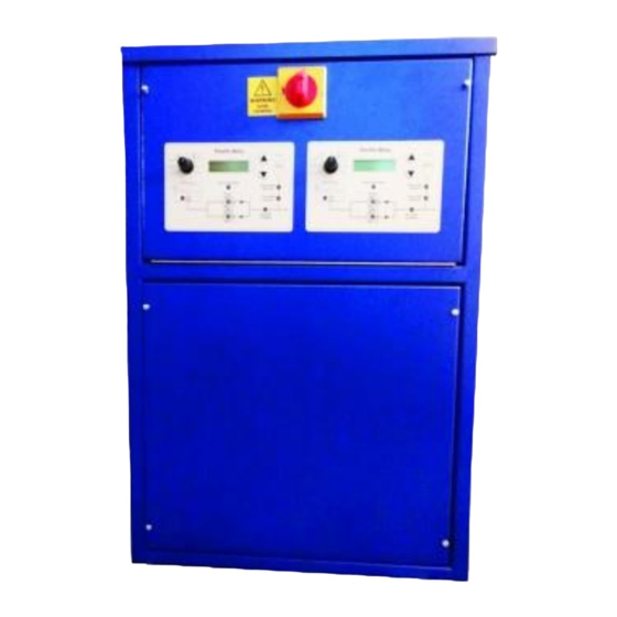
Page 5: Operation
Operation Ensure MCBs in the electrical section are at the on position, switch selector switch on front panel to Auto. Switch main isolator on front door to the on position. The digital display will now go through the starting check sequence, after about 8 seconds the display will show system pressure. - Page 6 Typical MTHW sealed system max. 120°C. Intermediate vessel only required on MTHW systems www.pumpsukltd.co.uk | info@pumpsukltd.co.uk Units 3-4 Invicta Park, Sandpit Road, Dartford, Kent, DA1 5BU...
-
Page 7: Fault Finding Guide
Fault finding guide Fault Possible Cause Remedy Pump fails to start Power supply failure Control panel fuse blown, Reinstate incoming power supply MCB tripped Replace power supply fuse Remote inhibit active Reset MCB Low water level Turn remote inhibit off Reinstate water supply Pump fails to stop Set point set too high Manual operation selected... - Page 8 Single Pump Wiring Diagram www.pumpsukltd.co.uk | info@pumpsukltd.co.uk Units 3-4 Invicta Park, Sandpit Road, Dartford, Kent, DA1 5BU...
- Page 9 Twin Pump Wiring Diagram www.pumpsukltd.co.uk | info@pumpsukltd.co.uk Units 3-4 Invicta Park, Sandpit Road, Dartford, Kent, DA1 5BU...
- Page 10 Dual System Wiring Diagram www.pumpsukltd.co.uk | info@pumpsukltd.co.uk Units 3-4 Invicta Park, Sandpit Road, Dartford, Kent, DA1 5BU...
Need help?
Do you have a question about the PUK Autopress 1LC and is the answer not in the manual?
Questions and answers