Table of Contents
Advertisement
Quick Links
Advertisement
Table of Contents

Related Manuals for Carestream HEALTH CS 9000

Summary of Contents for Carestream HEALTH CS 9000
- Page 1 CS 9000 AND CS 9000 3D User Guide...
- Page 2 Congratulations on your purchase of the CS 9000 and CS 9000 3D. Thank you for your confidence in our products and we will do all in our power to ensure your complete satisfaction. The CS 9000 and CS 9000 3D User Guide includes information both on the Panoramic features as well as the features.
-
Page 3: Table Of Contents
Preparing the Unit and Setting the Acquisition Parameters ........5–7 CS 9000 and CS 9000 3D User Guide (SM764)_Ed 01... - Page 4 Cleaning the CS 9000 or CS 9000 3D Unit ....... .
-
Page 5: 1-About This Guide
Alerts you to a condition that might cause serious damage. IMPORTANT Alerts you to a condition that might cause problems. NOTE Emphasizes important information. Provides extra information and hints. CS 9000 and CS 9000 3D User Guide (SM764)_Ed 01 1–1... - Page 6 Conventions in this Guide 1–2 About This Guide...
-
Page 7: 2-Cs 9000 And Cs 9000 3D Unit Overview
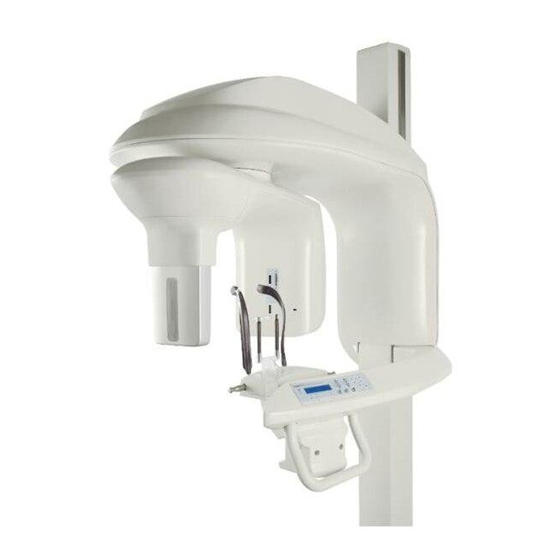
Chapter 2 CS 9000 AND CS 9000 3D UNIT OVERVIEW The CS 9000 and CS 9000 3D units are designed to carry out the following radiological examinations: • Panoramic • Maxillary Sinus • Temporomandibular Joints (TMJ) • 3D images General Overview The CS 9000 unit is composed of the following functional components: •... -
Page 8: Mobile Components
General Overview Mobile Components Figure 2-1 illustrates the up and down movement of the CS 9000 and CS 9000 3D mobile component and the 180° rotation of the rotative arm. Figure 2–1 CS 9000 and CS 9000 3D Unit Mobile Components 2–2... -
Page 9: General Functional Components
General Overview General Functional Components Figure 2-2 illustrates the general functional components of the CS 9000 and CS 9000 3D units. Figure 2–2 CS 9000 and CS 9000 3D Unit Functional Components ON/OFF button Temple supports Unit fixed arm Sensor... -
Page 10: Digital Sensor Locations
Therefore, the location of the digital sensor indicates that it is ready for the 3D option. Figure 2–3 CS 9000 and CS 9000 3D Unit Panoramic and 3D Digital Sensor Locations Digital 3D 2–4 CS 9000 AND CS 9000 3D UNIT OVERVIEW... -
Page 11: Laser Locations
General Overview Laser Locations Figure 2-4 illustrates the location of the CS 9000 and CS 9000 3D lasers. Figure 2–4 CS 9000 and CS 9000 3D Unit Laser Beam Positions 3D central positioning laser beam Mid-sagittal positioning laser beam Horizontal positioning laser beam... -
Page 12: Unit Control Panel
Display Screen: Displays the current acquisition parameters and the error messages. Ready Indicator LED: Green, indicates the unit is ready for acquisition. X-Ray Emission LED: Yellow, indicates the X-rays are being emitted. System Status LED: Red, indicates the error alerts. 2–6 CS 9000 AND CS 9000 3D UNIT OVERVIEW... -
Page 13: X-Ray Remote Control Overview
X-ray room. You must press and hold the exposure button until the end of acquisition. Premature release of the exposure button interrupts the acquisition. Figure 2–6 X-Ray Remote Control Exposure button: launches image acquisition. CS 9000 and CS 9000 3D User Guide (SM764)_Ed 01 2–7... -
Page 14: Positioning Accessories And Replacement Parts
Positioning Accessories and Replacement Parts Positioning Accessories and Replacement Parts The following accessories are used when positioning a patient. They are delivered with the CS 9000 and CS 9000 3D digital imaging unit. Panoramic Positioning Accessories Table 2–1 Panoramic Positioning Accessories and Replacement Parts... -
Page 15: 3D Positioning Accessories
3D Positioning Accessories and Replacement Parts Accessory Description 3D bite block 3D bite block support 3D head rest and head strap Single use hygienic sheaths for 3D bite block (100 pcs box) CS 9000 and CS 9000 3D User Guide (SM764)_Ed 01 2–9... -
Page 16: Patient Positioning Indicators
Patient Positioning Indicators represented on the chin rest base Positioning Indicators Description For sinus positioning • For TMJ x2 and TMJ x4 positioning • For panoramic positioning For 3D upper jaw positioning For 3D lower jaw positioning 2–10 CS 9000 AND CS 9000 3D UNIT OVERVIEW... -
Page 17: 3-Imaging Software Overview
It is MANDATORY to check that the computer system configuration is compatible with the minimum computer system requirements for the CS 9000 and CS 9000 3D software. If necessary you MUST update your computer system configuration. CS 9000 and CS 9000 3D MUST be connected to the computer via a point-to-point ethernet link NOT via a LAN. -
Page 18: Acquisition Interface
Acquisition Interface Acquisition Interface Panoramic Acquisition Interface Overview The Panoramic Acquisition interface is the main panoramic interface with CS 9000 and CS 9000 3D and provides you with imaging acquisition functions. Figure 3–1 Panoramic Acquisition Interface Information button: • About: Identifies the software and the firmware versions •... - Page 19 The Selector button enables you to access the following 3 panes: • Program pane: Examination type options • Patient pane: Patient type parameter options • Parameters pane: Exposure parameter options CS 9000 and CS 9000 3D User Guide (SM764)_Ed 01 3–3...
-
Page 20: Panoramic Program Pane
Acquisition Interface Panoramic Program Pane The Panoramic Program pane enables you to choose different radiological exams. The diagram in the Panoramic Program pane represents a jaw, with the right side of the diagram corresponding to the right side of the patient. Click on a section of the jaw to select an anatomical zone for radiological examination. -
Page 21: Panoramic Patient Pane
Incisors orientation. Click: for a vestibular orientation. for an axial orientation. for a lingual orientation. CS 9000 and CS 9000 3D User Guide (SM764)_Ed 01 3–5... -
Page 22: Panoramic Parameters Pane
Acquisition Interface Panoramic Parameters Pane The Panoramic Parameters pane enables you to choose exposure parameters for the radiological image acquisition. If the default parameter setting is not adapted to your patient’s type, you can manually adapt the parameter settings to the patient’s type and save this setting as the default setting. -
Page 23: 3D Acquisition Interface Overview
Acquisition Interface 3D Acquisition Interface Overview The 3D Acquisition interface is the main 3D interface with the CS 9000 3D that provides you with imaging acquisition functions. 3D Acquisition interface Figure 3–5 Information button: • About: Identifies the Software and the Firmware versions •... - Page 24 Acquisition Interface X-Ray Emission Indicator: Yellow indicates the X-ray emission status. Exit button: Closes the Acquisition window. Validation button: Validates the selected region of interest. Cancellation button: Cancels the selected region of interest. Selector button: Selects different acquisition setting options. Click: •...
-
Page 25: 3D Program Pane
Multi-Volume button: Enables you to access the multi-volume Program pane. Validation button: Click to validate the region of interest selection. Cancellation button: Click to cancel the region of interest selection. CS 9000 and CS 9000 3D User Guide (SM764)_Ed 01 3–9... -
Page 26: 3D Patient Pane
Acquisition Interface 3D Patient Pane The 3D Patient pane enables you to choose different patient parameters. The selection of the patient parameters influences the quality of the image. The selected parameters must be based on the age and morphology of the patient. Figure 3–8 3D Patient Pane Patient type parameters. -
Page 27: 3D Parameters Pane
3D Parameter Pane Radiation dose options: kV: kilovolt mA: milliampere Fine-tuning buttons. Click: to fine-tune the kV, the mA and the µm (voxel) Image resolution options: µm (voxel): micrometer CS 9000 and CS 9000 3D User Guide (SM764)_Ed 01 3–11... - Page 28 Acquisition Interface 3–12 IMAGING SOFTWARE OVERVIEW...
-
Page 29: 4-Getting Started
3. Leave the X-ray room and close the door. For each parameter setting, from the X-ray remote control, press and hold the button to launch the X-ray. The unit is now ready to be used for acquisition. CS 9000 and CS 9000 3D User Guide (SM764)_Ed 01 4–1... -
Page 30: Accessing The Acquisition Windows
Accessing the Acquisition Windows Accessing the Acquisition Windows To access the Acquisition windows, follow these steps: 1. In the Imaging window, from the toolbar, click to access the Panoramic Acquisition window, or, click to access the 3D Acquisition window. 2. See the chapter “Acquiring an Image” to launch an acquisition. 4–2 GETTING STARTED... -
Page 31: 5-Acquiring Images
5. Press and hold to raise the chin rest to the following positioning indicators: • For a panoramic or TMJ x2 positioning • For a sinus positioning CS 9000 and CS 9000 3D User Guide (SM764)_Ed 01 5–1... -
Page 32: Preparing And Positioning The Adult And Pediatric Patient
Acquiring a Panoramic, TMJ x2 or Sinus Image for Adult and Pediatric Patients Preparing and Positioning the Adult and Pediatric Patient To prepare and position the patient, follow these steps: 1. Ask the patient to remove all metal objects. 2. Ask the patient to wear a lead apron with a thyroid collar. Ensure that the apron lays flat across the patient’s shoulders. - Page 33 The spinal column and the nose of the patient must be aligned in a straight line (1). 7. Correctly align the Frankfort and midsagittal planes using and the adjusting thumb wheel. CS 9000 and CS 9000 3D User Guide (SM764)_Ed 01 5–3...
- Page 34 Acquiring a Panoramic, TMJ x2 or Sinus Image for Adult and Pediatric Patients 8. Immobilize the patient’s head with the temple supports (3). 9. Ask the patient to do the following: • close their eyes • remain still • swallow •...
-
Page 35: Launching The X-Ray
4. Do the following when the acquisition is finished: • Open the temple supports and release the patient. • Remove the hygienic sheath from the bite block. • Reset the unit rotative arm for the next acquisition. CS 9000 and CS 9000 3D User Guide (SM764)_Ed 01 5–5... -
Page 36: Acquiring A Tmj X4 Image For Adult And Pediatric Patients
Acquiring a TMJ x4 Image for Adult and Pediatric Patients Acquiring a TMJ x4 Image for Adult and Pediatric Patients Before acquiring a TMJ x4 image, check that you have: • Reset the unit rotative arm to the start position for patient to enter the unit. •... -
Page 37: Acquiring A 3D Single-Volume Image For Adult And Pediatric Patients
The selected parameter will be saved automatically as default value. 4. Position the 3D bite block support and 3D standard bite block and cover the bite block with a hygienic sheath. CS 9000 and CS 9000 3D User Guide (SM764)_Ed 01 5–7... - Page 38 Acquiring a 3D Single-Volume Image for Adult and Pediatric Patients 5. Press and hold to raise the chin rest to the following positioning indicators: • For an upper jaw positioning • For a lower jaw positioning 5–8 ACQUIRING IMAGES...
-
Page 39: Manually Pre-Setting The Single-Volume Position For Adult And Pediatric Patients
4. Remove the plaster imprint and position the patient in the unit and follow the appropriate steps to acquire the 3D image of the region of interest. CS 9000 and CS 9000 3D User Guide (SM764)_Ed 01 5–9... -
Page 40: Preparing And Positioning Adult And Pediatric Patients
Acquiring a 3D Single-Volume Image for Adult and Pediatric Patients Preparing and Positioning Adult and Pediatric Patients To prepare and position the patient, follow these steps: 1. Ask the patient to remove all metal objects. 2. Ask the patient to wear a lead apron with a thyroid collar. Ensure that the apron lays flat across the patient’s shoulders. - Page 41 3D FoV (2) positioning laser beam. Tighten the temple supports (3). 8. Ask the patient to close their eyes, remain still and breath through their nose. CS 9000 and CS 9000 3D User Guide (SM764)_Ed 01 5–11...
-
Page 42: Launching The X-Ray
Acquiring a 3D Single-Volume Image for Adult and Pediatric Patients Launching the X-ray To launch the X-ray, follow these steps: 1. Leave the X-ray room and close the door. You must keep visual contact with the patient during acquisition. IMPORTANT To stop the acquisition, if there is any problem, release the exposure button of the remote control or press the red emergency stop button. -
Page 43: Acquiring A 3D Multi-Volume Image (Stitching) For Adult And Pediatric Patients
To remove a region of interest indicator, click on the indicator. IMPORTANT The 3 regions of interest indicators displayed are fixed and not modifiable. CS 9000 and CS 9000 3D User Guide (SM764)_Ed 01 5–13... - Page 44 Acquiring a 3D Multi-Volume Image (Stitching) for Adult and Pediatric Patients 5. Select the following regions of interest according to the desired exam: • Full arch (by default), covering a zone of 7cm (depth) x 8 cm (Width): ± ± •...
-
Page 45: Preparing And Positioning Adult And Pediatric Patients
Relax their shoulders for full motion of the unit rotative arm 5. Ask the patient to bite gently and naturally into their own bite registration on the 3D bite block. CS 9000 and CS 9000 3D User Guide (SM764)_Ed 01 5–15... - Page 46 Acquiring a 3D Multi-Volume Image (Stitching) for Adult and Pediatric Patients 6. Click on the Control Panel to turn ON the positioning laser beams. Adjust the patient using the following 2 positioning laser beams: • The midsagittal (1) positioning laser beam •...
-
Page 47: Launching The X-Ray
You can release the patient after acquiring each region of interest. In this case, you must make sure that the height of the 3D bite block and the position of the unit rotative arm remains unchanged. CS 9000 and CS 9000 3D User Guide (SM764)_Ed 01 5–17... - Page 48 Acquiring a 3D Multi-Volume Image (Stitching) for Adult and Pediatric Patients 3. When is green, press and hold the exposure button until the end of the second region of interest acquisition. The turns yellow, indicating X-ray emission. The image appears in the Preview Screen. 4.
-
Page 49: X-Ray Dose Emission Information
The radiation emission dose is expressed in mGy.cm . This dose is measured at the primary collimator outlet. The dose is accurate to ±30%. The primary slot is 0.5 mm wide and 18.2 mm high. CS 9000 and CS 9000 3D User Guide (SM764)_Ed 01 5–19... - Page 50 X-Ray Dose Emission Information 5–20 ACQUIRING IMAGES...
-
Page 51: Quick Troubleshooting
I 16 Incorrect positioning of This error applies only to Raise the chin rest to the maximum height. the chin rest panoramic mode. CS 9000 and CS 9000 3D User Guide (SM764)_Ed 01 6–1... - Page 52 Quick Troubleshooting Table 6–2 Quick Troubleshooting (Continued) Information Error Code Information Message Description Action I 17 Sensor in movement The sensor is in the positioning Wait for the end of the positioning process. process for either panoramic, 3D or Ceph mode. I 18 Unidentified Sensor The Sensor is incorrectly...
-
Page 53: Daily
Chapter 7 MAINTENANCE Perform the following maintenance activities on your CS 9000 or CS 9000 3D unit. Daily Cleaning the CS 9000 or CS 9000 3D Unit To clean the CS 9000 or CS 9000 3D unit, follow these steps: 1. -
Page 54: Cleaning And Disinfecting The Accessories
Daily Cleaning and Disinfecting the Accessories CAUTION You MUST cover the Panoramic standard bite block and the bite block for edentulous patients with FDA-cleared protective sheaths that are available from distributors. We recommend that you cover the TMJx4 nose rest and the 3D bite block with FDA-cleared protective sheaths that are available from distributors. -
Page 55: Cleaning And Disinfecting The Components And Accessories That Have Skin Contact
Monthly Wipe the outer covers of the unit with a soft dry cloth. Annually We recommend a general inspection of the unit carried out by an authorized service technician. CS 9000 and CS 9000 3D User Guide (SM764)_Ed 01 7–3... -
Page 56: Controlling The Image Quality
Controlling the Image Quality Controlling the Image Quality To maintain optimum image quality, the image quality must be controlled regularly. To control the image quality, follow these steps: 1. On your desktop, double-click . The Calibrations and Quality Control Software window is displayed. 2. - Page 57 Acceptance test: This test is ONLY executed by the technician. It is a complete image quality control test (make sure you have the required test tools). The result of this test is used as reference for the Constancy test by the user. CS 9000 and CS 9000 3D User Guide (SM764)_Ed 01 7–5...
- Page 58 Controlling the Image Quality 7–6 MAINTENANCE...
Need help?
Do you have a question about the CS 9000 and is the answer not in the manual?
Questions and answers