Table of Contents
Advertisement
Quick Links
Advertisement
Table of Contents

Summary of Contents for EKSMA OPTICS DQ-100-4
- Page 1 DQ-100-4 High Voltage Driver Technical Description 2021 Lithuania...
- Page 2 www.eksmaoptics.com...
-
Page 3: Table Of Contents
ONTENTS CHAPTER 1 WARRANTY 1.1. W ARRANTY TATEMENT 1.2. S ERVICE ONTACT NFORMATION CHAPTER 2 SPECIFICATIONS 2.1. G ENERAL NFORMATION 2.1.1. Model 2.1.2. Main Components 2.2. T ECHNICAL PECIFICATIONS CHAPTER 3 DEVICE LAYOUT CHAPTER 4 SAFETY CHAPTER 5 QUICK START GUIDE CHAPTER 6 IMPORTANT NOTES... - Page 4 IST OF IGURES 1. O ............3 IGURE UTLINE DRAWING AND DIMENSIONS OF THE DRIVER 2. T ....................4 IGURE OP VIEW OF THE DRIVER 3. I ....................7 IGURE NPUT CIRCUIT OF DRIVER 4. C ....................7 IGURE ONTROL TIMING CHARTS IST OF ABLES 1.
-
Page 5: Chapter 1 Warranty
Chapter 1 W ARRANTY This Pockels cell driver DQ-100-4 is protected by one-year warranty covering labor and parts. The warranty enters into validity since the shipment date. Any evidence of improper use or unauthorized attempts at repair leads to warranty cancellation. -
Page 6: Chapter 2 Specifications
Chapter 2 S PECIFICATIONS DQ-100-4 Table 1. Main components Component Quantity DQ-100-4 High voltage (HV) driver Set of DC power and sync. Cable (l=1.5m) DQ-100-4 HV cable (l=1.5m; soldered to Technical description Table 2. Technical specifications Parameter Specifications Maximum working voltage (HV), kV... -
Page 7: Chapter 3 Device Layout
Chapter 3 D EVICE AYOUT Figure 1. Outline drawing and dimensions of the driver... -
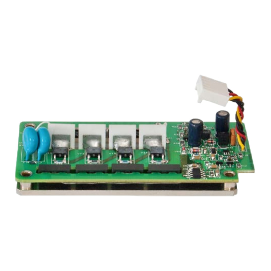
Page 8: Figure 2. Top View Of The Driver
Figure 2. Top view of the driver Table 3. Ports seen in top view of the driver Port Connector for DC power suppling and HV driving Pin1 SYNC IN input Pin2 GND Pin3 +DC power input Pin4 N.C. Pin5 GND HV pulse output pin +OUT GND output pin +HV Power input pin... -
Page 9: Chapter 4 Safety
Chapter 4 S AFETY Equipment is designed to be safe under normal environmental conditions according to 1.4.1. 61010-1@IEC:2010 (Safety requirements for electrical equipment, control and laboratory use): a) indoor use; b) altitude up to 2000 m; c) temperature 5ºC to 35˚C; d) maximum relative humidity 80% for temperatures up to 31ºC decreasing linearly to 50% relative humidity at 35ºC;... -
Page 10: Chapter 5 Quick Start Guide
6. Provide synchronization pulses from the generator It is necessary to measure the generator output voltage with a 50 load before applying synchronization signals to the DQ-100-4 driver. The signal voltage must be in the range of 3.5…5 V. -
Page 11: Figure 3. Input Circuit Of Driver
After the generator output voltage is measured, remove the 50 load and provide synchronization pulses to the driver. Figure 3. Input circuit of driver Figure 4. Control timing charts... -
Page 12: Chapter 6 Important Notes
Chapter 6 I MPORTANT OTES Please read these important notes before using the product! 1. The output pulse is provided between OUT and GND connectors. Do not connect an oscilloscope or any other device to the OUT connector. The wire contact with the Pockels cell must be proper in order to avoid a discharge, which may to damage the driver.
Need help?
Do you have a question about the DQ-100-4 and is the answer not in the manual?
Questions and answers