Table of Contents
Advertisement
Quick Links
Advertisement
Table of Contents

Related Manuals for Scott Safety HushAir Connect 7500

Summary of Contents for Scott Safety HushAir Connect 7500
- Page 1 HushAir Connect 7500 COMPRESSOR SYSTEM User Guide 087-0067 Rev A...
- Page 3 HushAir Connect 7500 User Guide COMPRESSOR SYSTEM 087-0067 Rev A...
- Page 4 Scott Safety. Scott Safety reserves the right to revise this documentation and to make changes in content from time to time without obligation on the part of Scott Safety to provide notification of such revision or change.
-
Page 5: Table Of Contents
Settings ............SCOTT SAFETY... - Page 6 Specifications ........... . . Support PPENDIX 087-0067 REV A SCOTT SAFETY...
- Page 7 ............SCOTT SAFETY...
- Page 8 CONTENTS 087-0067 REV A SCOTT SAFETY...
- Page 9 Breathing Air Cylinder Markings ....... . . SCOTT SAFETY 087-0067 REV A...
- Page 10 Oil Drain Location ......... . . 087-0067 REV A SCOTT SAFETY...
- Page 11 LIST OF TABLES Scott Safety Documentation Set ....... . xiii Hush Air Connect 7500 User Guide Revision History .
- Page 12 LIST OF TABLES 087-0067 REV A SCOTT SAFETY...
-
Page 13: About This Guide
Configuration and Setup • Operation • Maintenance • Specifications • Support Warning: Read, understand and follow the entire content of this guide prior to use. Failure to do so may result in serious injury or death. SCOTT SAFETY 087-0067 REV A... -
Page 14: Guide Conventions
This icon and text indicate the possibility of electrostatic discharge (ESD) in a procedure that requires the reader to take the proper ESD precautions. This icon and text designates information of special note. 087-0067 REV A SCOTT SAFETY... -
Page 15: Related Product Documentation
Related Product Documentation Related Product Table 1 lists the Scott Safety Family documentation set. Documentation Table 1 Scott Safety Documentation Set DOCUMENT NAME PURPOSE DOCUMENT ID SCOTT SAFETY 087-0067 REV A... -
Page 16: Revision History
ABOUT THIS GUIDE Revision History Table 2 shows the revision history for this guide, providing a description of the changes. Table 2 Hush Air Connect 7500 User Guide Revision History REVISION CHANGE Initial release 087-0067 REV A SCOTT SAFETY... -
Page 17: Certifications And Approvals
Approvals standards, or standardized documents. Table 3 Certifications and Approvals SYMBOL SPECIFIC DIRECTIVES, STANDARDS CAN/CSA-C22.2 No. 68-09 Motor-Operated Appliances Household and Commercial UL 1450 3rd Edition Motor Operated Aire Compressors, Vacuum Pumps and Painting Equipment. SCOTT SAFETY 087-0067 REV A... - Page 18 FCC’s RF exposure limits for general population / uncontrolled exposure. The CPU on the charge station has been assigned FCC ID # PD94965AGN. SUBPART C INTENTIONAL RADIATORS FCC Part 15.247 and OET 65 087-0067 REV A SCOTT SAFETY...
-
Page 19: General Safety Information
Caution: The air produced by this equipment must be recertified periodically as meeting CGA Grade D or better breathing quality air. Regular recertification to this standard is the responsibility of the user. SCOTT SAFETY 087-0067 REV A... - Page 20 Warning: If the device does not function as described herein, remove from service and mark for maintenance. Only use Scott Safety replacement parts. Scott Safety can take no responsibility for use of its equipment if it is not used in accordance with the instructions. If further operational or maintenance details are required but not provided in this guide, contact Scott Safety or their agent.
-
Page 21: Warnings And Cautions - Working With Compressed Air
Warning: Before use, this equipment must be properly installed and inspected by a Scott Safety trained and certified technician. Do not operate if the equipment has not been prepared by a Scott authorized service technician. Use of this equipment without proper set up may result in serious personal injury, death, or permanent equipment damage. - Page 22 Caution: Electric power supply must be installed in accordance with local, state, and federal electrical code requirements. Warning: Compressed air can kill. Treat it with respect. 087-0067 REV A SCOTT SAFETY...
-
Page 23: Introduction
087-0067 Chapter 1 Rev A INTRODUCTION Chapter Overview This chapter covers the following topics: • Overview • Theory of Operation SCOTT SAFETY 087-0067 REV A... -
Page 24: Overview
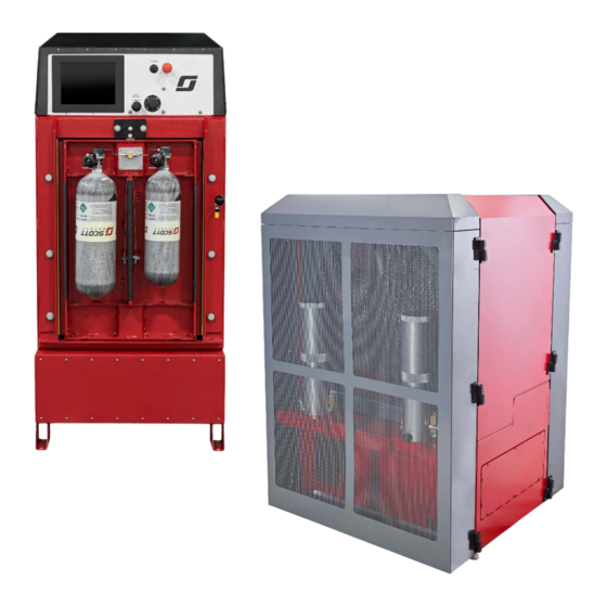
HMI, and storage. Additionally, based on your needs, either single component may be used as a standalone device. The HushAir Connect 7500 is the compressor, the RevolveAir Connect is the charge station and the SmartTouch Controller is the HMI. -
Page 25: Compressor System Categories
440VAC/3P H/50Hz 460VAC/3P H/60Hz A standalone compressor includes the items in Table 4 plus a DP monitor, a CO monitor and a wall mounted LCD. Figure 1 shows the major parts of a compressor example. SCOTT SAFETY 087-0067 REV A... - Page 26 Motor Saver - Optional feature depending on the model. Protect 3-phase motors from: high voltage, low voltage, voltage unbalance, reverse-phase, overcurrent, undercurrent, current unbalance, single-phase, ground fault, Class II. 087-0067 REV A SCOTT SAFETY...
- Page 27 First Stage Safety Relief Value - To release high pressure air to protect the compressor in case of mechanical failure. This specific value pertains to the first stage of the process. Interconnect Cable - Provides communications between devices. *Note: Not all models are equipped the same. SCOTT SAFETY 087-0067 REV A...
-
Page 28: Charge Station Models
1 allowed None selection 8004451 Automatic Single 1 allowed selection * Note: PSI output options are selected from the following: 2216, 3000, 4500, or 5500 Figure 2 shows the major parts of a charge station example. 087-0067 REV A SCOTT SAFETY... - Page 29 Pressure Regulator - Controls the pressure output to the SCBA. For use only by service technician. USB Port - Allows access to data log and their transferring. RFID Access Level - Allows access selected from four (4) levels (Manufacturer, Service, Supervisor and User). SCOTT SAFETY 087-0067 REV A...
-
Page 30: Storage Unit Example
Table 8 Storage Unit Example NUMBER OF CASCADE CYLINDER CERTIFIED CYLINDERS METHODS HOUSING MOUNTED STANDARD 2 or 4 Automatic, Rack Vertical ASME manual or bulk Figure 3 shows the major parts of a storage example. 087-0067 REV A SCOTT SAFETY... -
Page 31: Storage Unit Major Parts Example
Rack Mount - Intended to bolt on to a charge station. *Note: Not all models are equipped the same. “Specifications” on page 87. If you have any questions about the models or their operation contact Scott Safety. See “Technical Service” on page 92. SCOTT SAFETY... -
Page 32: Theory Of Operation
The charge station allows the simultaneous filling of two (2) cylinders while two (2) additional cylinders can be attached and made ready on the outside of the chamber. 087-0067 REV A SCOTT SAFETY... -
Page 33: Installation
087-0067 Chapter 2 Rev A INSTALLATION Chapter Overview This chapter covers the following topics: • Planning for Installation • Installation Checklist • Locating and Securing the Devices • Wiring the Devices SCOTT SAFETY 087-0067 REV A... -
Page 34: Planning For Installation
Caution: RFI may be generated if wires are not appropriately shielded or share conduit with other AC power conductors. Protect wires with appropriate shielding practices to prevent negative equipment performance. 087-0067 REV A SCOTT SAFETY... -
Page 35: Installation Checklist
18. “Locating the Compressor” on page 14. Compressor Locating “Securing the Compressor” on page 15. Securing “Wiring the Compressor” on page 19. Wiring “Securing the Storage Unit” on page 15. Storage Unit Secure SCOTT SAFETY 087-0067 REV A... -
Page 36: Locating And Securing The Devices
Warning: Make sure there is nothing close to or on top of the Compressor that could interfere with the air flow. For proper operation, the minimum clearance of 24” must 087-0067 REV A SCOTT SAFETY... -
Page 37: Securing The Compressor
The bolts are 58113 HH Wedge Anchor GR5 Z (5/8-11 X 3 Hex Head Wedge Anchor Bolt Grade 5 Zinc). Warning: When applicable, the Storage Unit must be anchored to the floor using the supplied bolts. Failure to do so could result in injury or death. SCOTT SAFETY 087-0067 REV A... -
Page 38: Wiring The Devices
Do not modify the plug provided; if it does not fit the outlet, have the proper outlet installed by a qualified electrician. Figure 4 Wiring Overview - System Charge Station Compressor Interconnect Cable 120VAC 208,230/ 460VAC-3PH, 60Hz 230,380/ 440VAC-3PH, 50Hz 60AMPS Max 087-0067 REV A SCOTT SAFETY... -
Page 39: Wiring The Charge Station
RFID Read/Write Scanner - Allows scanning of the RFID tags that contain data related to the cylinder. Green LED - Indicates power is supplied. Green/Red LED - Indicates communication between the RFID Read/Write Scanner and the PC. SCOTT SAFETY 087-0067 REV A... -
Page 40: Installing The Rfid Read/Write Software
See Figure Not all models support the RFID functions and thus this section may or may not be applicable. Ensure the RFID Read/Writer Scanner hardware in installed first for operation. Figure 7 RFID Read/Write Software 087-0067 REV A SCOTT SAFETY... -
Page 41: Wiring The Compressor
Wiring the Devices Wiring the This section covers the wiring the Compressor. Figure 8 shows the required power to Compressor be supplied by the end user for the Compressor. Figure 8 Wiring Diagram - Compressor SCOTT SAFETY 087-0067 REV A... - Page 42 CHAPTER 2: INSTALLATION 087-0067 REV A SCOTT SAFETY...
-
Page 43: Configuration And Setup
This chapter covers the following topics: • Using the HMI • User Access Levels • Using the Compressor HMI • Using the Charge Station HMI • Configuring the System • Using the RFID Read/Write Software SCOTT SAFETY 087-0067 REV A... -
Page 44: Using The Hmi
Warning: Configuration should be performed by trained individuals who have read this manual and understand the calibration procedures. Failure to follow these instructions may result in serious injury or death. Warning: When settings are changed, ensure those changes are communicated to all affected personnel. 087-0067 REV A SCOTT SAFETY... -
Page 45: User Access Levels
• Supervisor: This user is a customer selected individual to be in charge of the system. Access includes: to setup the list of designated users, setup and reset SCOTT SAFETY 087-0067 REV A... - Page 46 “Using the Charge Station HMI” on page 32. For the purposes of this guide, the Supervisor elements are discussed. However, since the User level is a subset it will be included by default. Access levels determine the display of some parameters. 087-0067 REV A SCOTT SAFETY...
-
Page 47: Using The Compressor Hmi
• Stop - Is used to manually shut down the compressor in an orderly manner. When activated, the cool down cycle of the compressor, if needed and then power down the remainder of the system. SCOTT SAFETY 087-0067 REV A... -
Page 48: Alerts - Screen
Each alert produces an associated audible alarm via the horn. These reflect the factory default settings. See Table 087-0067 REV A SCOTT SAFETY... -
Page 49: Alerts With Override Default Settings - Compressor
(1Hr) press Stage 590 to 0 to 30Sec % of Up to 3 620psig 120Sec output (1Hr) press Stage 1300 to 0 to 40Sec % of Up to 3 1550psig 120Sec output (1Hr) press SCOTT SAFETY 087-0067 REV A... -
Page 50: Alerts Without Override Events - Compressor
Fails at a specific compressor stage level Solenoid Value Fails • Information - Displays applicable information based on either standalone of a compressor or charge station or a combination. Typically this covers the status of specific parameters. See Table 087-0067 REV A SCOTT SAFETY... -
Page 51: Information Types - Compressor
Warning: Be sure that the input electrical power supply is correct for the system to be powered. All electrical supply wiring must be performed by a qualified electrician and SCOTT SAFETY 087-0067 REV A... -
Page 52: Pre-Operation Checklist - Compressor
Check the compressor for any loose components operation, or components at least once a week Remote air Check Before each Check the Remote Air Intake for any leaks intake operation, or at least once a week 087-0067 REV A SCOTT SAFETY... - Page 53 • Alerts - Displays the gas type, live reading, and the unit of measure. • Gas Reading - Displays the gas type, live reading, and the unit of measure. SCOTT SAFETY 087-0067 REV A...
-
Page 54: Using The Charge Station Hmi
Cylinder 2 - Displays the serial number, rated duration in minutes, pressure in PSI, hydro test date, last fill date and a graphic representation related to the SCBA being filled on the left side. • Non RFID Mode - 087-0067 REV A SCOTT SAFETY... -
Page 55: Alerts With Override Default Settings - Charge Station
100 to 600F 0 to 60Sec 15Sec 470F 495F Up to 3 550F Temp (1Hr) eratur Crank 100 to 600F 0 to 60Sec 15Sec 325F 338F Up to 3 345F 2min case (1Hr) High Temp eratur SCOTT SAFETY 087-0067 REV A... - Page 56 0 to 60Sec 2Sec 5ppm 5ppm Slip-I 0 to 60Sec 15Sec SW Signal SW Signal n door Close Comp 0 to 60Sec 5Sec SW Signal SW Signal ressor Enclo sure Open Incom Motor Saver Power Irregu 087-0067 REV A SCOTT SAFETY...
-
Page 57: Alerts Without Override Events - Charge Station
Typically this covers the pre-operation checklist.To ensure the reliability of the compressor, the operator is responsible for observing the unit during operation and performing checks as described. See Table 19 lists the pre-operation items. See Figure SCOTT SAFETY 087-0067 REV A... -
Page 58: Pre-Operation Checklist - Charger Station
Lock Out/Tag Out of the circuit breaker or master switch. 087-0067 REV A SCOTT SAFETY... - Page 59 Check the Remote Air Intake for any leaks intake operation, or at least once a week Note: Anderol 500 oil is a registered trademark of Anderol, Inc. and XL-700 oil is a registered trademark of Ingersoll-Rand Company. SCOTT SAFETY 087-0067 REV A...
-
Page 60: Configuring The System
This only allows viewing the parameters. No changes are allowed. See Figure Screen content varies depending on the system. That is, if the system is a standalone Compressor, or standalone Charge Station or, a combination of both a Compressor and a Charge Station. 087-0067 REV A SCOTT SAFETY... -
Page 61: System Info Screen
Charge Station - Displays various configurable parameters including: charge station type, and preset fill pressure. Both the alerts and pre-operation checklist icons shown on this various configuration screens are duplications of those already covered in other sections. SCOTT SAFETY 087-0067 REV A... -
Page 62: Settings
This section covers the various settings of the system. Used to configure the settings. It includes: CO Calibration, Charge Station, Compressor, Preferences, Customer User Management. Charge Station includes: General Settings and Pressure Calibration. Compressor includes: General Settings and Pressure Calibration. CO Calibration Figure 087-0067 REV A SCOTT SAFETY... -
Page 63: Configuration - Co Calibration Screen
Warning: Carefully thread regulator onto cylinder port. Cross threading may damage threads and/or overtightening may damage sealing gasket resulting in leaks. This leakage may expose user to carbon monoxide calibration gas resulting in serious injury or death. SCOTT SAFETY 087-0067 REV A... -
Page 64: Charge Station
Toggle Horn - Allows changing its state. The individual state status of on or off is displayed below. • Individual State Status - Various state status are displayed based on user actions or the device’s parameter state. 087-0067 REV A SCOTT SAFETY... -
Page 65: Charge Station - Pressure Calibration Screen
• Reset Selected Sensor - • Set Low Pressure - • Set Mid Pressure - • Set High Pressure - • Pressure Select Solenoid1 - • Pressure Select Solenoid2 - • Fill Pressure Solenoid - SCOTT SAFETY 087-0067 REV A... -
Page 66: Compressor
Toggle Horn - Allows changing its state. The individual state status of on or off is displayed below. • Toggle Drain - Allows changing its state. The individual state status of on or off is displayed below. 087-0067 REV A SCOTT SAFETY... -
Page 67: Compressor - Pressure Calibration Screen
Scaling Max - • Sensor Range Type - • Minimum Display Value - • Low Alarm Limit - • Override Shutdown Alarm Limit - • Stage Out of Range Delay - • Zero Selected Sensor - SCOTT SAFETY 087-0067 REV A... -
Page 68: Preferences
Max Shutdown Alarm Value - • Update Shutdown Alarm Preferences Figure Figure 22 Preferences Screen • Preference - Displays various configurable parameters including: language, units and time zone. All of the parameters on this screen are read only. 087-0067 REV A SCOTT SAFETY... -
Page 69: Customer
Configuring the System Customer Figure Figure 23 Customer Screen • Customer Information - Displays various configurable parameters including: name, location, contact into region and last service date. All of the parameters on this screen are read only. SCOTT SAFETY 087-0067 REV A... -
Page 70: User Management
Email ID - A unique qualifier for each user. • User Credential - Shows the user’s first and last name. • Passcode - A unique 6 digit number for each user. • User Level - Selects from the four (4) access levels. 087-0067 REV A SCOTT SAFETY... -
Page 71: Overrides
• Switches - Displays various configurable parameters including: stationary door and vent door. Allows changing its state. The individual state status of on or off. All of the parameters on this screen can be written. SCOTT SAFETY 087-0067 REV A... -
Page 72: Override Settings Screen
CHAPTER 3: CONFIGURATION AND SETUP Figure 26 Override Settings Screen • Exit Application - Allows exiting back to the logon screen. 087-0067 REV A SCOTT SAFETY... -
Page 73: Override Status Screen
Configuring the System Figure 27 Override Status Screen SCOTT SAFETY 087-0067 REV A... -
Page 74: Using The Rfid Read/Write Software
To Write data to the Tag, enter the data into the fields on the screen, then press the Write RFID Tag to Write the data. • To Read data from the Tag, press the Read RFID Tag button on the screen. 087-0067 REV A SCOTT SAFETY... -
Page 75: Operation
087-0067 Chapter 4 Rev A OPERATION Chapter Overview This chapter covers the following topics: • Compressor Overview • Charge Station Overview • Storage Overview SCOTT SAFETY 087-0067 REV A... -
Page 76: Compressor Overview
The purification system further dries the air and removes other impurities. After this, the breathable air may go directly to a charge station, to fill SCBA cylinders, or may be sent to ASME high pressure storage cylinders. 087-0067 REV A SCOTT SAFETY... -
Page 77: Compressor Interfaces
Warning: Hearing protection may be required when using the Stationary Air Compressor system for extended periods of time. Refer to the personal safety SCOTT SAFETY 087-0067 REV A... - Page 78 8 When the system reaches maximum pressure, the compressor runs a cool down cycle for two (2) minutes. During this time, the compressor runs unloaded while draining the moisture separators, and cooling down the compressor stages. After 087-0067 REV A SCOTT SAFETY...
-
Page 79: Compressor E-Stop Button
In the Emergency Shutdown mode, the compressor is locked out and unavailable for four (4) minutes. Repeated use of the Emergency Shutdown results in residual moisture in the system which may result in serious damage to the equipment. SCOTT SAFETY 087-0067 REV A... -
Page 80: Charge Station Overview
The system opens and closes the storage cylinders to efficiently use all the available air to fill the breathing air cylinders. The operation of the Auto Cascade system does not require additional tasks or adjustments by the operator. 087-0067 REV A SCOTT SAFETY... -
Page 81: Charge Station Interfaces
For more details, See “Configuration and Setup” on page 21. Figure 30 Charge Station Screen Example Warning: When settings are changed, ensure those changes are communicated to all affected personnel. SCOTT SAFETY 087-0067 REV A... -
Page 82: Charge Model Interfaces
USB Port - Allows access to data log and their transferring. Schrader Valve - To take sample of air. E-Stop - Manually shuts down the compressor. Horn - Alarms indicating important events. For details regarding the HMI, See “Configuration and Setup” on page 21. 087-0067 REV A SCOTT SAFETY... - Page 83 Compressor Pressure Analog Gauge - Indicates the compressor pressure. Storage Pressure Analog Gauge - Indicates the storage pressure. Schrader Valve - To calibrate CO. Schrader Valve - To take sample of air. Dual Pressure Toggle Switch - Selects between the two pressures. SCOTT SAFETY 087-0067 REV A...
- Page 84 Compressor Pressure Analog Gauge - Indicates the compressor pressure. Storage Pressure Analog Gauge - Indicates the storage pressure. Schrader Valve - To calibrate CO. Schrader Valve - To take sample of air. 087-0067 REV A SCOTT SAFETY...
-
Page 85: Charging The Scba Cylinders
3 Verify that the compressor or storage pressure is greater than the fill pressure of the selected breathing air cylinder. If pressure is too low, allow the compressor system to continue building pressure. See Figure 34 Table SCOTT SAFETY 087-0067 REV A... - Page 86 4 When system pressure is adequate to fill the breathing air cylinders, unlock the fill station door by operating the handle (item 1) on the right side of the chamber (Yellow lock bars not showing). See Figure 087-0067 REV A SCOTT SAFETY...
-
Page 87: Charging Chamber Unlocked
A damaged cylinder may rupture, and can cause serious personal injury or death. 6 Close both bleed valves (item 1) on the fill station “finger tight” (one bleed valve on each side of the fragmentation chamber door). Do not use tools to tighten. See Figure SCOTT SAFETY 087-0067 REV A... - Page 88 Dual Pressure. Failure to use the correct pressure setting may result in serious damage to the cylinder or cylinder valve. A damaged cylinder may rupture, and can cause serious personal injury or death. 087-0067 REV A SCOTT SAFETY...
-
Page 89: Cylinders Mounting And Charging
5 Open the charging chamber door lock by operating the handle on the right side of the chamber so that the Yellow lock bars are not showing. 6 Rotate the chamber door 180° until it clicks into position. See Figure SCOTT SAFETY 087-0067 REV A... -
Page 90: Rotating Camber Door
11 Leave the fill pressure and fill rate set when charging several cylinders that require the same fill pressure and fill rate. Minor adjustments may be necessary during filling of successive cylinders depending on the compressor system used. 087-0067 REV A SCOTT SAFETY... - Page 91 Failure to do so will cause cylinders to be in an overcharge condition, increasing the risk of cylinder failure and leading to personal injury or death. SCOTT SAFETY 087-0067 REV A...
-
Page 92: Storage Overview
The fill station may be installed with storage cylinders or a manual or an automatic cascade system. See “Automatic Cascade” on page 58. See “Storage Cylinder Inspection” on page 74. Read and follow all safety labels on the unit. 087-0067 REV A SCOTT SAFETY... -
Page 93: Storage Interfaces
The time required for charging the air storage system depends on the number and pressure rating of the storage cylinders. If cylinder pressure does not build properly, contact a Scott certified service technician to troubleshoot the system. SCOTT SAFETY 087-0067 REV A... - Page 94 To isolate a cascaded cylinder, simply turn the control valve clockwise to shut off the air flow. Turn the valve counterclockwise to allow the compressed air to flow as normal. 087-0067 REV A SCOTT SAFETY...
-
Page 95: Maintenance
087-0067 Chapter 5 Rev A MAINTENANCE Chapter Overview This chapter covers the following topics: • Storage Cylinder Inspection • Breathing Air Cylinder Inspection • Maintaining the Compressor • Troubleshooting the Compressor SCOTT SAFETY 087-0067 REV A... -
Page 96: Storage Cylinder Inspection
National Bureau of Standards (NB) and a tamper evident seal. Some Scott storage systems with ASME storage cylinders are protected by single use rupture disks that cannot be tested. Refer to specific ASME or DOT safety standards for additional testing information. 087-0067 REV A SCOTT SAFETY... -
Page 97: Breathing Air Cylinder Inspection
2 Visually inspect cylinder and valve assembly for physical damage such as dents or gouges in metal or in composite wrapping. Cylinders which show physical damage or exposure to high heat or flame, such as paint turned brown or black, decals SCOTT SAFETY 087-0067 REV A... - Page 98 3 Always check the pressure rating of the selected breathing air cylinder(s) to be filled. The rated pressure usually follows the DOT or TC material identification as shown. See Figure 46 Table 087-0067 REV A SCOTT SAFETY...
-
Page 99: Maintaining The Compressor
Filter (Break-in) Crankcase Oil Change Crankcase Oil Filter Change Drive Belt System X**** (Inspection) Exercise Relief Valves (All) Hardware and X**** Fastener Inspection Inspect for X**** Oil/Air Leaks Intake Element X**** Inspection Intake Element Replacement SCOTT SAFETY 087-0067 REV A... - Page 100 **** Note: The first 90 days inspection and service requires the assistance of a Scott Certified Technician. ***** Note: Use only Anderol 500 oil or XL-700 oil, available from your local Scott distributor. AR= As Required. 087-0067 REV A SCOTT SAFETY...
-
Page 101: Draining The Condensate Container
1 If the compressor is running, press the Stop key on the control panel to stop the compressor. 2 Remove the container from under the compressor frame and pour condensate out from the hose connection spout. 3 Dispose of condensate according to hazardous waste regulations. SCOTT SAFETY 087-0067 REV A... -
Page 102: Replacing The Fuses
If the replaced fuse blows in a short time, secure the compressor system with your lock-out/tag-out procedures and notify a Scott trained and certified service technician to perform a thorough system check before using the system again. Always use the proper rated fuse. Figure 42 Fuses Location 087-0067 REV A SCOTT SAFETY... -
Page 103: Resetting The Motor Saver
The output pressure from Stage 5 is monitored for safety. When the pressure output reaches 7,300PSI the compressor is disabled. To enable the compressor, press the High Pressure Reset button on the outside of the electrical control box. See Figure Figure 44 High Pressure Button Location SCOTT SAFETY 087-0067 REV A... -
Page 104: Checking The Inlet Filter
Purification Filters The purification filters should be checked to ensure they are in good operating conditions. They should be replaced as needed by Scott trained and certificated service technician. See Figure Figure 46 Purification Filter Location 087-0067 REV A SCOTT SAFETY... -
Page 105: Checking The Drive Belt
5 Remove the crankcase breather/filler top (3). 6 Pure the new oil into the crankcase breather/filler. 7 Replace the top of the crankcase breather/filler. 8 Turn the bleed value clockwise. SCOTT SAFETY 087-0067 REV A... -
Page 106: Oil Drain Location
CHAPTER 5: MAINTENANCE Figure 48 Oil Drain Location 087-0067 REV A SCOTT SAFETY... -
Page 107: Troubleshooting The Compressor
Troubleshooting the Refer to Table 29 for troubleshooting assistance. Compressor Warning: If the device does not function properly, remove from service and mark for maintenance. Only use Scott Safety replacement parts. Table 29 Troubleshooting Matrix SYMPTOM CAUSE SOLUTION Excessive stage 1 Faulty suction or 1 Service value(s) as needed. - Page 108 5 Belt too tight or too loose. Adjust as needed. Or moisture content oil or grease on belt. Clean or replace vee belts. in air. 5 Belt wear. Extended 1 Machine not 1 Check for leaks. running. large enough or leaks. 087-0067 REV A SCOTT SAFETY...
-
Page 109: Specifications
087-0067 Appendix A Rev A SPECIFICATIONS Appendix Overview This appendix covers the following topic: • Specifications SCOTT SAFETY 087-0067 REV A... -
Page 110: Specifications
18 scfm to 29 scfm Inlet Pressure Atmospheric Oil Pressure 35 to 60 PSI Material Aluminum Dimensions 62.43Hx43.0Wx42.59”D (1589.8Hx1092.2Wx1081.8Dmm) Weight 20HP: 1,450Lbs. (657.71Kg) 10HP: 1,193Lbs. (541.14Kg) ° ° Operating Temperature 15.0 to +125 F (-9.4 to +51.6 087-0067 REV A SCOTT SAFETY... - Page 111 Supported Cylinders ASME Vertical Material Rack: Steel frame, plastic cover Cylinder: Steel • Dimensions For 2 Cylinder: 65.67Hx33.86Wx26.25”D (1668.1Hx860.1Wx666.75Dmm) • For 4 Cylinder: 65.67Hx33.86Wx29.98”D (1668.1Hx860.1Wx761.5Dmm) Weight Rack with 4 tanks: 1,909Lbs. (865.91Kg) Cylinder: 400Lbs. (181.43Kg) SCOTT SAFETY 087-0067 REV A...
- Page 112 APPENDIX A: SPECIFICATIONS 087-0067 REV A SCOTT SAFETY...
-
Page 113: Support
087-0067 Appendix B Rev A SUPPORT Appendix Overview This appendix covers the following topics: • Technical Service • Limited Warranty SCOTT SAFETY 087-0067 REV A... -
Page 114: Technical Service
APPENDIX B: SUPPORT Technical Service Congratulations on your purchase of a Scott Safety product. It is designed to provide you with reliable trouble-free service. Contact us, if you have technical questions, need support, or if you need to return a product. - Page 115 Beijing branch, Shanghai Eagle Safety Equipment Co. Ltd. Suite 708, Scitech Tower, No.22 Jianguomenwai Avenue, Chaoyang District, Beijing, 100004, P.R.China Telephone: +86-10-65150005 Asia Scott Safety – Asia Service Dept 2 Serangoon North Ave 5, #07-01 Singapore 554911 Telephone: +65 6883 9671 Fax:+65.
-
Page 116: Limited Warranty
APPENDIX B: SUPPORT Limited Warranty Scott Safety (SCOTT), warrants the Compressor, Charge Station and Storage (THE PRODUCTS) to be free from defects in workmanship and materials for a period of five (5) years from the date of original manufacture by SCOTT or 1000 hours whichever comes first. -
Page 117: Index
Purification Filter Storage Unit Login Screen Firmware Version Major Parts Example Fuses Charge Station Location Compressor Storage Unit Matrix Troubleshooting General Safety Models Charge Station Information xvii Guide Conventions Motor Saver Button Guide Overview Location SCOTT SAFETY 087-0067 REV A... - Page 118 RFID Read/Write Screen RFID Read/Write Software Storage Unit Example Major Parts Example Technical Support Contact Information Troubleshooting Matrix Warnings and Cautions Device Use and Care Working with Compressed Air Working with Compressed Air Warnings and Cautions 087-0067 REV A SCOTT SAFETY...
- Page 120 Monroe Corporate Center P.O. Box 569 Monroe, NC 28111 Telephone: 800-247-7257 FAX: (704) 291-8330 Web: www.scottsafety.com...
Need help?
Do you have a question about the HushAir Connect 7500 and is the answer not in the manual?
Questions and answers