
Summary of Contents for Ama Tech SUN-7.6K-SG01LP1-US
- Page 1 HYBRID INVERTER MANUAL Hybrid Inverter SUN-7.6K-SG01LP1-US/EU SUN-8K-SG01LP1-US/EU SUN-6K-SG01LP1-US SUN-5K-SG01LP1-US User Manual...
- Page 2 S E R V I C E S & P R O D U C T S P V M O D U L E S P L A N N I N G S T R I N G I N V E R T E R S H Y B R I D I N V E R T E R S D E S I G N &...
- Page 3 M a n u a l C o n t e n t 1. Safety Instructions 4. OPERATION 4.1. Power ON/OFF 2. Product Instructions 4.2. Operation and Display Panel 2.1 Product Overview 2.2 Product Features 6. Mode 5. LCD Display Icons 2.3 Basic System Architecture 5.1.
-
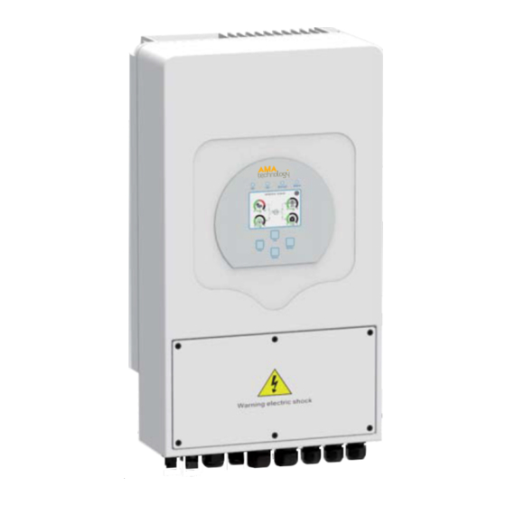
Page 4: Product Overview
S A F E T Y I N S T R U C T I O N S P R O D U C T O V E R V I E W 1. Safety Instructions 2.1. Product Overview This chapter contains important safety and operating instructions. Read and keep this •... -
Page 5: Product Features
P R O D U C T F E A T U R E S B A S I C S Y S T E M A R C H I T E C T U R E 2.2. Product Features 2.3. -
Page 6: Installation
I N S T A L L A T I O N 3. INSTALLATION 3.1. Parts List Please Check the equipment before installation. Make sure nothing is damaged in the package. You should have received the following items in the package: Description Delivery Date: SUN-5K/6K-SG01LP1-US hybrid inverter... -
Page 7: Mounting The Inverter
M O U N T I N G I N S T R U C T I O N S 3.2. Mounting Instructions Considering the following points before selecting Mounting the inverter Installation Precaution where to install: Please select a vertical wall with load-bearing capacity for installation, suitable for •... -
Page 8: Battery Connection
B A T T E R Y C O N N E C T I O N 3.3.2. Battery temperature Connection 3.3. Battery Connection Please follow below steps to implement battery connection: For safe operation and compliance, a separate DC 1. -
Page 9: Ac Input/Output Connection
A C I N P U T / O U T P U T C O N N E C T I O N 3.4. AC Input/Output Connection Please follow below steps to implement AC input/output connection: Before connecting to AC input power source, please install a separate AC breaker between inverter and AC input 1. - Page 10 P V C O N N E C T I O N 3.5. PV Connection 3.5.2. PV Module Wire Connection 3.5.1. PV Module Selection Before connecting to PV modules, please install a separately Please follow below steps to implement PV module connection: When selecting proper PV modules, please be sure to DC circuit breaker between inverter and PV modules.
-
Page 11: Wifi Connection
C T & E A R T H C O N N E C T I O N 3.6. CT Connection Note: Note: 3.7. Earth Connection (mandatory) When the inverter is in the off-grid state, the N line needs to When the inverter is in the off-grid state, the N line needs to Ground cable shall be connected to ground plate on grid side be connected to the earth. - Page 12 W I R I N G S Y S T E M F O R I N V E R T E R ( R E G I O N E U ) 3.9. Wiring System for Inverter (Region: EU) Fig.
- Page 13 W I R I N G S Y S T E M F O R I N V E R T E R ( R E G I O N U S ) 3.9. Wiring System for Inverter (Region: US) Fig.
- Page 14 3.10.-1-: Single Phase Parallel Connection Diagram (Region: EU) 3.11.: Split Phase Parallel Connection Diagram (Region: US) Fig. 3.10.: Fig. 3.11.: Region EU Region US – 11 –...
- Page 15 T H R E E P H A S E P A R A L L E L I N V E R T E R 3.12. Three Phase Parallel Inverter Fig. 3.12.: Three Phase Parallel Inverter – 12 –...
-
Page 16: Operation And Display Panel
O P E R A T I O N L C D D I S P L A Y I C O N S 4. OPERATION 4.1. Power ON / OFF Once the unit has been properly installed and the batteries are connected well, simply press ON/OFF button (located on the left side of the case) to turn on the unit. When system without battery connected, but connected with either PV or grid, and ON/OFF button is switched off, LCD will still light up (Display will show OFF). - Page 17 L C D O P E R A T I O N F L O W C H A R T S O L A R P O W E R C U R V E 5.1.1. LCD Operation Flow Chart 5.2.
-
Page 18: System Setup Menu
C U R V E P A G E : S O L A R , L O A D , G R I D , T O T A L S Y S T E M S E T U P M E N U 5.3. -
Page 19: Battery Setup Menu
B A T T E R Y S E T U P M E N U 5.6. Battery Setup Menu Lithium Battery Batt Mode ——————Lithium Max A Charge ———— 0 – 185A Lithium Mode ————This is BMS protocol. Default is 0 please Max A Discharge ———0 –... - Page 20 S Y S T E M W O R K M O D E S E T U P M E N U G R I D S E T U P M E N U 5.8. Grid Setup Menu 5.7.
- Page 21 G E N E R A T O R P O R T U S E S E T U P M E N U & A D V A N C E D F U N C T I O N S E T U P M E N U & D E V I C E I N F O S E T U P M E N U 5.9.
- Page 22 M O D E S : I B A S I C / I I W I T H W I N D T U R B I N E / I I I W I T H G E N E R A T O R / I V W I T H S M A R T L O A D / V W I T H O N - G R I D I N V E R T E R 6.
- Page 23 F A U L T I N F O R M A T I O N A N D P R O C E S S I N G & E R R O R C O D E S : D E S C R I P T I O N S + S O L U T I O N S 7.
-
Page 24: Limitation Of Liability
F A U L T I N F O R M A T I O N A N D P R O C E S S I N G | L I M I T A T I O N O F L I A B I L I T Y I N S T A L L A T I O N C O M P A N Y 7. - Page 25 H Y B R I D I N V E R T E R F O R S O L A R A P P L I C A T I O N S W E D E L I V E R O U R B E S T Hybrid Inverter SUN-7.6K-SG01LP1-US/EU SUN-8K-SG01LP1-US/EU SUN-6K-SG01LP1-US...
- Page 26 D A T A S H E E T : S U N - 7 . 6 K - S G 0 1 L P 1 - U S / E U S U N - 8 K - S G 0 1 L P 1 - U S / E U S U N - 6 K - S G 0 1 L P 1 - U S S U N - 5 K - S G 0 1 L P 1 - U S 9.
Need help?
Do you have a question about the SUN-7.6K-SG01LP1-US and is the answer not in the manual?
Questions and answers