
Related Manuals for Kowa nonmyd WX 3D


Summary of Contents for Kowa nonmyd WX 3D
- Page 1 GG-10003 Edition 1.3 Edition 1.3 2017.5 K9L57 (D90 model) Model Name: K9L57F9 (D5200 model) Model Name:...
-
Page 3: Table Of Contents
GG-10003 Edition 1.3 Contents 1. Name of each component ・・・・・・・・・・・・・・・・・・・・・・・・・・・・・・・・・・・・・・・・・ 2. Monitor Screen Indications ・・・・・・・・・・・・・・・・・・・・・・・・・・・・・・・・・・・・・・・・ 3. Optical pathways・・・・・・・・・・・・・・・・・・・・・・・・・・・・・・・・・・・・・・・・・・・・・・・・・ 4. Wiring Diagram ・・・・・・・・・・・・・・・・・・・・・・・・・・・・・・・・・・・・・・・・・・・・・・・・・ 5. Preparing for Part Replacement ・・・・・・・・・・・・・・・・・・・・・・・・・・・・・・・・・・・・ Removing outer cover ・・・・・・・・・・・・・・・・・・・・・・・・・・・・・・・・・・・・・・・ Removing the power supply ・・・・・・・・・・・・・・・・・・・・・・・・・・・・・・・・・・ Removing the optical head base ・・・・・・・・・・・・・・・・・・・・・・・・・・・・・・ Configuration of electrical component・・・・・・・・・・・・・・・・・・・・・・・・・・... -
Page 4: Name Of Each Component
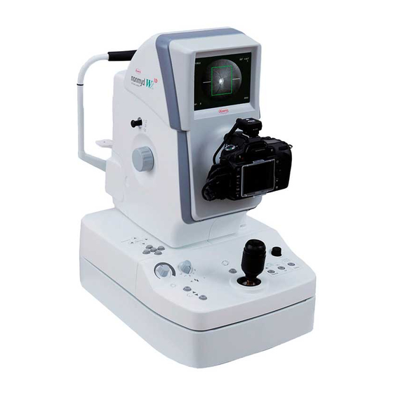
GG-10003 Edition 1.3 1. Name of each component... - Page 5 GG-10003 Edition 1.3...
-
Page 6: Monitor Screen Indications
GG-10003 Edition 1.3 2. Monitor Screen Indications... -
Page 7: Optical Pathways
GG-10003 Edition 1.3 3. Optical pathways LED for objective lens cleaning (green) Illumination Lens for anterior alignment Mirror Mirror with hole Internal fixation LED Patient’s eye Objective lens Ring slit (Normal/Stereo) Black point glass (Normal/Stereo) Ring slit (Normal/Stereo) LED for focusing aid (Infra-red) Flash lamp Mirror... -
Page 8: Wiring Diagram
GG-10003 Edition 1.3 4. Wiring Diagram... -
Page 9: Preparing For Part Replacement
GG-10003 Edition 1.3 5. Preparing for Part Replacement Removing outer cover *Always turn off the power switch before removing the outer cover. ●Optical head cover 1 Remove the caps of the left and right focus knobs with a (-) driver. 2... - Page 10 GG-10003 Edition 1.3 ●Optical head base cover and panel cover Remove five screws and then one of the optical head base covers. And also remove the other optical head base cover. Raise and extract a panel cover. ※Be careful not to damage joystick.. Remove the cable of the panel cover from the cable clamping.
-
Page 11: Removing The Power Supply
GG-10003 Edition 1.3 Removing the power supply cover *Always turn off the power switch and pull the plug from the socket. 1 Remove the outer cover beforehand. 2 Tighten the optical head base fixing screw. 3 Tighten the lock screw. 4... -
Page 12: Removing The Optical Head Base
GG-10003 Edition 1.3 6~7 Removing the optical head base *Always turn off the power switch and pull the plug from the socket. 1 Remove the outer cover beforehand. 2 Remove ten screws and then the insertion prevention board. 3 Remove two screws and then the stoppers(left and right). 4... -
Page 13: Configuration Of Electrical Component
GG-10003 Edition 1.3 5-4. Configuration of electrical component 【Optical component】 Right side Left side LCD A U K9L57 #5251 Internal fixation U K9L57 #5240 FD LED PCB K9L57 #5050H SUB PCB K9L57 #5160 Main PCB K9L57 #5150 Discharge PCB K9L57 #7055A 【power supply unit】... -
Page 14: Replacing Parts
GG-10003 Edition 1.3 6. Replacing parts Replacing parts list ① The main body relation ①-1 ①-2 ①-3 Main board SUB board Discharge board K9L57 #5150 K9L57 #5160 K9L57 #7055A ①-4 ①-5 ①-6 Int-Fix unit WD&Vis LED AnteLED K9L57 #5240 *HC-K9L57-5170 *HC-K9L57-5150 ①-7... - Page 15 GG-10003 Edition 1.3 ①-13 ①-14 ①-15 LCD A unit Optical head fan Objective lens K9L57 #5251 *HC-K9L57-5120 K9L39 #9037D Monaural and stereo ①-16 ①-17 ①-18 ANGLE solenoid Obs LED solenoid *HC-K9L57-5020 *HC-K9L57-5250 *HC-K9L57-5260 ①-19 ①-20 ①-21 IR CCD camera Mask solenoid FD mirror solenoid BE-IR30N-S2 *HC-K9L57-5310...
- Page 16 GG-10003 Edition 1.3 ② The optical head base relation ②-1 ②-2 ②-3 XeTRG board Optical head motor Menu switch board K9L57 #7101E *HC-K9L57-5240 K9L39 #9110B Lamp volume and ②-4 ②-5 ②-6 Joystick Friction tray flash switch *HC-K9L57-5060 ER80 #1330 K9L39 #750 Optical head motor ②-7...
- Page 17 GG-10003 Edition 1.3 ③ Power supply relation Power supply board ③-1 HV board ③-2 ③-3 Interface board (SWPS) K9L57 #5830 K9L57 #5850 PMMK150S-12 ③-4 ③-5 ③-6 Power supply fan Capacitor H U TRANS_H HC-K9L57-0008 K9L57 #5820 *HC-K9L57-5440...
-
Page 18: Lens Cleaning
GG-10003 Edition 1.3 7. Lens cleaning Preparing for lens cleaning <Required items> -Cleaning solution-・・・・・Mixed solution of 50% absolute ethyl alcohol and 50% ether. ※Other lens cleaners may leave residue after cleaning. -Softwood stick-・・・・・・A softwood stick approximately 10 inches (25 cm) in length with its end shaved flat. -
Page 19: Lens Cleaning Procedures
GG-10003 Edition 1.3 Lens cleaning procedures ① Using the blower, blow dusts off from the lens. Air-blow cleaning is the principal cleaning method. Proceed to the steps below only when you need to remove stubborn soils that the air-blow cleaning cannot handle. ②... -
Page 20: Lens Cleaning Part And Cleaning Method
GG-10003 Edition 1.3 Lens cleaning part and cleaning method Objective lens Holed mirror Mirror A Anterior segment lens Focus lens Stereo and monaural switching rens Corneal lens Stereo focus lens Stereo and monaural Mirror B sunspot lens Mount protection glass B/W camera lens Digital camera Anterior... -
Page 21: Cleaning Of Object Lens
GG-10003 Edition 1.3 Cleaning the objective lens 1 Turn on a power supply switch. 2 Make the room dark so that dirt of an object lens is known well. 3 Hold down the center button more than 2 seconds to access the menu mode. 4... -
Page 22: Digital Camera Setting
GG-10003 Edition 1.3 Digital camera setting 8.1 D90 model camera settings Ensure that the digital camera settings are correctly configured. ※5 Use Main command dial to set the shutter speed. ※6 You may change Photo quality mode and Image size at your discretion. Photo quality mode : FINE, NORMAL, BASIC Image size : L, M, S ◇... -
Page 23: D5200 Model Camera Settings
GG-10003 Edition 1.3 8.2 D5200 model camera settings Ensure that the digital camera settings are correctly configured. Dial Setting Custom menu Menu items Setting Menu items Setting Mode dial No memory card? LOCK Focus-mode selector Focus selector lock Set-up menu ※... -
Page 24: Troubleshooting
The error message below is displayed on the LCD Charged voltage exceeded the limit. monitor. There could be a failure of an Please contact Kowa or your Kowa dealer. Error1: Higher Voltage internal circuit. Power OFF and Call Service Person... - Page 25 GG-10003 Edition 1.3 Problem Cause Remedy Connector improperly connected. Reconnect the connector of the USB cable. Faulty cable. Replace the USB cable. The USB hub is used. Reconnect the USB cable without using the USB hub. The digital camera is not Adjust the length of the total of accessory USB cable and performance recognized...
-
Page 26: ②Abnormality Concerning Display
Focus dots do not appear. Connector improperly connected. Reconnect the connector of the FD LED cable. Faulty cable. Replace the FD LED cable. Please contact Kowa or your Kowa dealer. Faulty solenoid. After replacing the FD mirror solenoid, mirror adjustment is needed. Focus... -
Page 27: ③Abnormality Concerning Photography Or Image
GG-10003 Edition 1.3 ③Abnormality concerning photography or image Problem Cause Remedy Connect synchronous cable (hot shoe) connector surely. Connector improperly connected. Flash lamp does not emit light even if the shutter switch Confirm that a power supply cable is connected to a pushed. - Page 28 Clean the objective lens or the lens underneath the hole dirt. mirror. White spots appear in the center picture Please contact Kowa or your Kowa dealer.After replacing Focus mirror malfunctioning.. photographed. the focus mirror solenoid, mirror adjustment will be (Faulty solenoid ) needed.
-
Page 29: How To Clean Up The Low-Pass Filter For Nikon D-Series
GG-10003 Edition 1.3 How to clean up the low-pass filter for Nikon D-series ―Automatic Cleaning― The image sensor that acts as the camera’s picture element is fitted with a low-pass filter to prevent moiré. If you suspect that dirt or dust on the filter is appearing in photographs, you can clean the filter using the [Clean image sensor] option in the setup menu. - Page 30 Although low-pass filter may be cleaned according to the procedures below; it is fragile and can be easily damaged. Cleaning by Kowa or a Kowa-designated service provider is recommended. 1. Turn OFF the power supply of Nikon D-series. 2. Disconnect the cable connected to Nikon D-series.
-
Page 31: How To Clean Up The Right And Left Detection Sensor
GG-10003 Edition 1.3 How to clean up the right and left detection Preparations Cleaning paper. Ruler (thickness around 1mm) of around 200mm. Bloy(air duster recommendation). Chopsticks. How to clean up the right-and-left detection board ① Move an optical head to the front left (inspection person side), and raise the navigational panel side of an optical head from the bottom. - Page 32 GG-10003 Edition 1.3 How to clean up the L/R sensor. ① Move an optical head to the front right (inspection person side), and raise the navigational panel side of an optical head from the bottom. ② Twist the dry cleaning paper around chopsticks. And wipe an L/R ensor with the chopsticks. (However, use neither water nor cleaning solution) ①...
-
Page 33: How To Adjust The Black Point Glass(For Stereo Mode
GG-10003 Edition 1.3 How to adjust the black point glass(for stereo mode) 1. Removing the cover of the optical component Refer to 「K9L57(nonmyd WX) Service Manual」 2. Replacement of the objective lens ① Remove the objective lens from the optical base after loosening screws (n=2). ②... - Page 34 GG-10003 Edition 1.3 ③ Clean the reflection side of the mirror with hole. ④ Clean the both side of the lens unit, which placed under the mirror with hole. ⑤ Clean the both side of the black point glasses. Black point glass (for normal mode) Black point glass (for stereo mode)
- Page 35 GG-10003 Edition 1.3 4. Confirmation of the center sun spot at stereo mode. ① Disconnect the connector, which is with tag “ANTE”, from the main PCB (HK1264). ② Release the anterior lens from optical pathway. Inside of the optical pathway Outside of the optical pathway ③...
- Page 36 GG-10003 Edition 1.3 ⑥ Go forward the optical head base. The flare gradually is getting disappeared. When push the shutter button, confirm that a ring is reflected on the blackboard (see the below image). (In that time the distance between object lens and blackboard is approximately 30mm then.) Then check the image.
- Page 37 GG-10003 Edition 1.3 ⑨ Adjust a holed mirror with three places of screws or two places like the chart below. a) When a slightly central spot appears, make a fine adjustment with three screws pointed by purple. (Adjustment by the quantity of push screw). b) When the central spot looks bigger, adjust it with two screws pointed by blue at first.
-
Page 38: How To Adjust The Black Point Glass (For Normal Mode)
GG-10003 Edition 1.3 How to adjust the black point glass(for normal mode) Removing optical head cover. Disassemble the shading covers after removing screws (n=7). Clean the lenses. Deviate the mirror from optical pathway and hold the mirror to remain the state. Set a digital camera of Nikon, and then connect each connector. - Page 39 GG-10003 Edition 1.3 Attach a focus knob. Turn a knob to the direction of the arrow enough. Set a flash bulb at "0" positions. Set a photography mode in normal. 10. Push a diopter revision knob, and have 0 positions. 11.
- Page 40 GG-10003 Edition 1.3...
Need help?
Do you have a question about the nonmyd WX 3D and is the answer not in the manual?
Questions and answers