
Related Manuals for Radeus 8000 ACS Series

Summary of Contents for Radeus 8000 ACS Series
- Page 1 Satellite Earth Station Antenna Control Systems Series 8000 ™ Operation & Maintenance ™ Model 8200 Antenna Control Unit ™ Model 8250 Drive Cabinet 26 APRIL 2022...
- Page 3 ™ Document rev. 20201022-1 Copyright © 2015 – 2020 Radeus Labs, Inc. All rights reserved. Subject to licensing terms. All contents of this publication are proprietary. They are not to be transmitted, shared, described, or conveyed in any way or form, in whole or in part, without advance written permission from Radeus Labs, Inc.
-
Page 4: Table Of Contents
C O N T E N T S Table of Contents Important Precautions ..................10 About This Document ..................11 Service and Support ..................... 11 ™ SERIES 8000 SETUP — OVERVIEW..........12 MODEL 8250 DRIVE CABINET ............13 Jog Controls at the Cabinet ............... 14 Power, Breakers, E-Stop .............. - Page 5 C O N T E N T S 3.5.4 Antenna Travel Limits ..................37 3.5.5 Motion Faults ....................40 3.5.6 Positioner ......................41 3.5.7 Timing ....................... 43 TYPICAL OPERATIONS ..............44 Touchscreen Display ................. 45 Start Up, Quit, Shut Down ..............47 4.2.1 Start the ACU application ................
- Page 6 C O N T E N T S 4.7.5 Manual jog ....................... 71 4.7.6 Track Immediate, Manual Peaking, and Bias Angles ........72 Update the ACU software ..............75 SYSTEM-FAULT CONDITIONS ............76 Faults and System Standby ............... 77 Respond to a Fault Condition ............79 Fault Messages &...
- Page 7 C O N T E N T S 5.3.19 "Polarization reversed" ................... 83 5.3.20 "Polarization encoder fault" ................83 5.3.21 "Polarization select in wrong position" ............83 5.3.22 "Polarization CCW soft travel limit" ..............83 5.3.23 "Polarization CW soft travel limit" ..............84 5.3.24 "Polarization travel limit switch tripped”...
- Page 8 C O N T E N T S 5.3.44 "Ephemeris data file needs update” "TLE ephemeris data file needs update” "IESS ephemeris data file needs update” ..............88 5.3.45 "Fault condition forced standby" ..............88 5.3.46 "Can't access settings file" ................88 5.3.47 "Can't access tracking history file"...
- Page 9 Customer Interface Block (CIB) Connections ........110 APPENDIX 5: SETUP: GD MODEL 253..........114 APPENDIX 6: SETUP: DTR ..............115 APPENDIX 7: SETUP: RADEUS SSC MODEL 3430 ......... 116 APPENDIX 8: SETUP: IRIG..............117 APPENDIX 9: SETUP: V1000 MOTOR DRIVES ........120 A-9.1 Reset the V1000 ................
- Page 10 TeamViewer Requirements ............. 156 A-14.3 SNMP ....................157 A-14.4 SNMP Requirements ............... 158 A-14.5 Commercial M&C software with Radeus Labs ACU support .... 159 A-14.6 Open source M&C software ............159 A-14.7 SNMP Tools ..................159 A-14.8 Serial M&C (7200 Request / Command M&C Protocol) ....160 A-14.9...
- Page 11 C O N T E N T S A-16.2 API key .................... 163 A-16.3 Testing API operation..............164 A-16.4 Get API version ................164 A-16.4.1 Postman ......................164 A-16.4.2 curl ........................165 A-16.4.3 Invoke-RestMethod ..................165 A-16.4.4 SSL CA certificate ................... 166 A-16.4.5 ACU domain name entry ................
-
Page 12: Important Precautions
Radeus Labs, Inc. shall not be responsible for injury or damage result- ing from or associated with improper use of its hardware or software or from its use by improperly trained or inexperienced individuals. -
Page 13: About This Document
About This Document Documentation for the Model 8200 antenna control unit (ACU) and Model 8250 drive cabinet from Radeus Labs, Inc. Service and Support To inquire about support and service options that are beyond the scope of this document: Radeus Labs, Inc. -
Page 14: Series 8000 Setup - Overview
I M P O R T A N T P R E C A U T I O N S 1 Series 8000 Setup — Overview ™ For detailed instructions, refer to the following sections. Series 8000™ O&M Manual... -
Page 15: Model 8250 Drive Cabinet
S E C T I O N 2 Model 8250 Drive Cabinet Also see Appendix 4: “Model 8250 Drive Cabinet.” This drive cabinet from Radeus Labs offers compelling advantages, but the Model 8200 ACU can be ordered with support for previous- generation GD (Vertex) 7150 cabinets. -
Page 16: Jog Controls At The Cabinet
8 2 5 0 D R I V E C A B I N E T Jog Controls at the Cabinet The Model 8250 has a jog panel with antenna jog controls similar to those on the front of the Model 8200 ACU. Model 8250’s jog panel inside the cabinet largely duplicates the jog Figure 2-2 panel of the Model 8200 ACU. -
Page 17: Power, Breakers, E-Stop
8 2 5 0 D R I V E C A B I N E T Power, Breakers, E-Stop In addition to the jog panel, above, more controls are shown in Figure . The E-Stop switch works by de-asserting the drive-enable line. Model 8250 power mains, breakers, and emergency stop Figure 2-3 Series 8000™... -
Page 18: Emergency Stop
8 2 5 0 D R I V E C A B I N E T 2.2.1 Emergency Stop • To stop all antenna motion as quickly as possible, push the red e-stop switch. • To release the e-stop, twist the knob clockwise. •... -
Page 19: Setting Up The Antenna Control Unit (Acu)
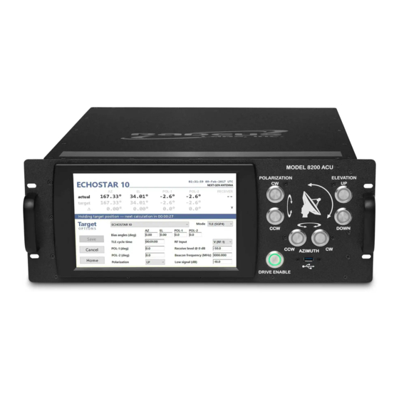
S E C T I O N 3 Setting Up the Antenna Control Unit (ACU) Antenna Control Unit (ACU) from Radeus Labs, Inc. Figure 3-1 Series 8000™ O&M Manual... -
Page 20: Retrofitting An Existing System
8 2 0 0 A C U S E T U P Retrofitting an existing system? Radeus Labs recommends replacing older position-feedback devices, e.g., resolvers or SSI optical encoders, with EnDAT optical encoders. Before installing the system Before proceeding with setup: •... -
Page 21: Connect The Acu
Connect the ACU Note: the location of the I/O controller (IOC) depends on whether the 8200 will be integrated with a Radeus Labs Model 8250 Drive Cabinet or other equipment — see “Model 8250 Drive Cabinet.” 1. Verify that the unit is connected to power. -
Page 22: Setup And Configuration
8 2 0 0 A C U S E T U P Setup and Configuration The Model 8200 includes a Setup Wizard. It can finish configuring ™ the system after you supply the essential data described in this section. The home screen offers access to all system settings and controls: The home screen of the ACU’s display. -
Page 23: Specify The Antenna & Location
8 2 0 0 A C U S E T U P 3.4.1 Specify the antenna & location Setup > Site Figure 3-4 Setup for required settings specific to the antenna. Except the first few tabs, they may be populated by the Setup Wizard. (“CP/LP se- lection”... -
Page 24: Antenna Polarization Settings
8 2 0 0 A C U S E T U P 3.4.2 Antenna Polarization Settings Some Series 2000 systems, such as the Model 2200, support various ™ Note n this document, polarization capabilities. Some systems have no POL fields; those with screenshots may two POL axes will display POL1 and POL2 fields. - Page 25 8 2 0 0 A C U S E T U P Specify which POL axes, if any, users are allowed to change from Figure 3-6 linear to circular polarization. • The period determines the maximum timeout for CP/LP switching (in milliseconds). To continue the setup, tap the Options tab.
-
Page 26: Options
8 2 0 0 A C U S E T U P 3.4.3 Options For HA-DEC antennas, see note below. In the event of a fault condition, text messages are displayed on the Figure 3-7 screen ( ). Optional audible alerts and sun-outage protec- Figure 4-2 tion can be enabled here. - Page 27 8 2 0 0 A C U S E T U P • Orbital tracking limit Constrains antenna control maneuvers to match the analemma trajectory of the target satellite (see ). When tracking a Figure 3-8 target whose trajectory brings it close to other satellites, orbital tracking limits can help avoid tracking nearby satellites uninten- tionally.
- Page 28 8 2 0 0 A C U S E T U P Brake control can be enabled in ACU.ini and then configured on the Figure 3-9 Setup > Options screen. • Brake control To enable this feature, edit the BRAKE key in the acu.ini file. (See Appendix 10: “Advanced Configuration —...
- Page 29 8 2 0 0 A C U S E T U P • Display units Provided for antennas that use hour angle and declination. This setting determines whether the ACU’s real-time data is shown in HA-DEC or AZ-EL units. (See Appendix 15: “Units: Hour Angle and Declination.”) Real-time data can be displayed in the native units of HA-DEC an- Figure 3-10...
-
Page 30: Enter The Receiver Characteristics
• Resolver — Appendix A-4.5 • DTR — Appendix 6: “Setup: DTR.” • GD 253 — Appendix 5: “Setup: GD Model 253.” • Radeus SSC Model 3430 — Appendix 7: “Setup: Radeus SSC Model 3430.” Setup > Receiver Figure 3-11 Specify the type of receiver being used, if any. - Page 31 8 2 0 0 A C U S E T U P 3.4.4.1 Analog receivers • Analog in 0dB ref (V) The analog input voltage for relative power level 0 dB. • Analog in slope (V/dB) The analog input’s slope (V/dBm). 3.4.4.2 “Internal”...
-
Page 32: Rf Inputs
8 2 0 0 A C U S E T U P 3.4.5 RF Inputs This screen is available only if Receiver Type, on the preceding tab, is set to Internal or Internal Ku. Use this to specify which axes are used for which in- put(s), and how they are labeled on the touchscreen. - Page 33 8 2 0 0 A C U S E T U P Figure 3-13 Choose a meaningful on-screen label for each input. • If the receiver type is Internal Ku, the default band is Ku. If the receiver type is Internal, the band must be specified. •...
-
Page 34: Specify Encoder Types And Positions
8 2 0 0 A C U S E T U P 3.4.6 Specify encoder types and positions For each axis, the encoder angle plus its offset equals the actual look angle. Required A position and direc- 1. Use the jog controls to point the antenna to a known or referenced tion must be entered look angle (e.g., a known satellite’s or star’s position, true north, for each encoder or... - Page 35 8 2 0 0 A C U S E T U P 4. “Ratio (encoder:axis)” — to enable this, edit the RATIOS key as in Appendix 10: “Advanced Configuration — acu.ini.” RATIOS=1 (the default is 0, for “off” — not enabled) Then you can choose from the drop-down menus the number of encoder/resolver-shaft revolutions for antenna movement along each axis:...
-
Page 36: Setup Wizard
8 2 0 0 A C U S E T U P Setup Wizard The Setup Wizard (see warning notes) can provide the other settings for the antenna. All settings can still be edited. Warning Do not run the Setup The Setup Wizard may be useful…... -
Page 37: How The Wizard Works
8 2 0 0 A C U S E T U P 3.5.2 How the wizard works Required: all limit switches must be in place before running the Setup Wiz- Setup details ard. The Setup Wizard will move the antenna through its full To view or edit set- range of motion —... -
Page 38: Run The Wizard
8 2 0 0 A C U S E T U P 3.5.3 Run the wizard First, complete the Setup screens for Site, Receiver (if present), RF In- How long will puts, and Encoders, and verify the wizard requirements, above. Then: it take? Precise times are site- 1. -
Page 39: Antenna Travel Limits
8 2 0 0 A C U S E T U P 3.5.4 Antenna Travel Limits Setup > Limits, and the Setup Wizard. See below to add the field for Figure 3-18 setting up sectors. • This screen gives access to the system’s soft travel limits. Among its tasks, the Setup Wizard sets a soft limit at 2°... - Page 40 8 2 0 0 A C U S E T U P After enabling sectors in acu.ini, the Setup > Limits tab allows the Figure 3-19 operator to swap between active Azimuth sectors. • “Sectors” — to enable this feature, edit AZ_SECTORS in acu.ini. (See Appendix 10: “Advanced Configuration —...
- Page 41 8 2 0 0 A C U S E T U P tion. This should be done prior to selecting the active sector on the ACU. For example, as shown in , below, sector A occupies Figure 3-20 the range 270° to 20°. Selecting sector B would change the ACU’s soft limits to the range 340°...
-
Page 42: Motion Faults
8 2 0 0 A C U S E T U P 3.5.5 Motion Faults Settings on the Motion tab determine when certain key fault condi- tions are asserted by the ACU. Setup > Motion Faults Figure 3-21 Settings that influence when certain system faults will be asserted. For each axis: •... -
Page 43: Positioner
8 2 0 0 A C U S E T U P 3.5.6 Positioner Setup > Positioner Figure 3-22 • Deadband The angle within which the controller will hold the axis. When the actual angle is within the deadband of a commanded posi- tion, the only antenna motions are momentary, “bump”... - Page 44 8 2 0 0 A C U S E T U P minimal effect on tracking behavior. To activate Eco mode: 1. Use the Home > Setup > Options tab to set Eco Mode to On. 2. On the Home > Setup > Positioner tab, enter the desired off- sets within which Eco mode will minimize small antenna ad- justments.
-
Page 45: Timing
8 2 0 0 A C U S E T U P 3.5.7 Timing Setup > Timing Figure 3-23 See section 3.4.3, “Options” to add the brake-control timings. • Bump duration — the amount of time to take a very small, meas- urable step in position. -
Page 46: Typical Operations
S E C T I O N 4 Typical Operations System configuration and all normal operations are carried out via the ACU’s touchscreen and hardware jog buttons. (Equivalent jog con- trols are provided in the Model 8250 drive cabinet.) Series 8000™ O&M Manual... -
Page 47: Touchscreen Display
T Y P I C A L O P E R A T I O N S Touchscreen Display The upper part of the touchscreen is for real-time data. It identifies the antenna, the targeted object, and position and signal information. The area below that is dedicated to controls and settings. - Page 48 T Y P I C A L O P E R A T I O N S the limit switches. • The “Receiver” area shows the relative signal strength, target beacon frequency, and signal level coming from the receiver. The system responds to fault conditions with messages (listed in section 5, “System-Fault Conditions”), and optional audible alert tones.
-
Page 49: Start Up, Quit, Shut Down
T Y P I C A L O P E R A T I O N S Start Up, Quit, Shut Down 4.2.1 Start the ACU application The ACU software starts when the unit powers on. If the power is on but the ACU software is not running: •... -
Page 50: Quit The Acu Application
T Y P I C A L O P E R A T I O N S 4.2.2 Quit the ACU application If a fault condition or some task requires quitting the ACU software, use the touchscreen’s Home > Setup > About screen and tap “Quit” to exit the ACU application and display the operating system desktop. -
Page 51: Power Down The Acu And Operating System
T Y P I C A L O P E R A T I O N S 4.2.3 Power down the ACU and Operating System To quit both the ACU application and the operating system, do so in an orderly manner: 1. -
Page 52: Define A New Target Satellite
T Y P I C A L O P E R A T I O N S Define a New Target Satellite To track a satellite, in most cases, the user selects it from a list on the ACU’s touchscreen. The process of defin- ing a target does not To add a satellite to the list of targets:... - Page 53 T Y P I C A L O P E R A T I O N S 3. In the Mode drop-down, select a mode to use for this target. Which input fields are displayed depends on the selected mode. Figure 4-5 The available modes are described in sections 4.6 and 4.7: •...
- Page 54 T Y P I C A L O P E R A T I O N S 4. Unless you’re using TLE or IESS data (section 4, “When peaked, tap Apply to save the new bias angles for that target, for use when it is acquired again later.
- Page 55 T Y P I C A L O P E R A T I O N S The list at Home > Target includes any operator-defined targets: Operator-defined targets are in the list at Home > Target. Figure 4-7 Series 8000™ O&M Manual...
-
Page 56: Default" And "Immediate" Targets
T Y P I C A L O P E R A T I O N S 4.4.1 “Default” and “Immediate” targets Two special-purpose items begin the list of targets displayed in the list of targets (for example, see Figure 4-4 •... -
Page 57: Edit A Target's Properties
T Y P I C A L O P E R A T I O N S Edit a Target’s Properties To change the settings for any target in the Home > Target list: The characteristics of targets can be edited. Figure 4-8 1. -
Page 58: Pointing Modes
T Y P I C A L O P E R A T I O N S Pointing Modes The mode is set on a per-target basis (see section 4.4). A pointing mode directs the antenna to a fixed location and actively holds that position. Also see section 4.7, “Tracking Modes.”... -
Page 59: Longitude Mode
T Y P I C A L O P E R A T I O N S 4.6.2 Longitude mode Much like look angles, except the initial angles are comput- ed from antenna data and the satellite’s box center longi- tude. - Page 60 T Y P I C A L O P E R A T I O N S 2. In place of the name-input text field, a drop-down list will pre- sent all TLE objects whose orbits will place them within range of the antenna’s soft limits any time in the next sidereal day.
- Page 61 T Y P I C A L O P E R A T I O N S Edit a TLE target’s settings to make any site-specific adjustments. Figure 4-12 3. For cycle time, enter the interval (HH:MM:SS) desired between calculations of the antenna’s next position. 4.
-
Page 62: Iess-412 - Intelsat Earth Station Standards
T Y P I C A L O P E R A T I O N S An operator must confirm before the antenna will change to a dif- Figure 4-13 ferent target. 4.6.4 IESS–412 — Intelsat Earth Station Standards The Model 8200 ACU supports IESS-412 data for targeting Intelsat spacecraft. - Page 63 T Y P I C A L O P E R A T I O N S Target missing? If a desired target is not shown in the drop-down list, check the values in Setup > Site > Antenna coordi- nates and in Setup >...
- Page 64 T Y P I C A L O P E R A T I O N S Settings for TLE (SGP4) or IESS-412 mode. Bias angles can be saved Figure 4-15 to more easily re-peak any target for which a pointing mode (i.e., not tracking) is used (see section 4.6.4.2).
- Page 65 The data may be updated over internal LAN. Choose Setup > About > Desktop to access Windows and ensure the directory at C:\Radeus Labs is shared with write permission. Copy geo.txt (for TLE) or satlist.csv (for IESS- 412) into it, from wherever it’s located on the LAN.
- Page 66 T Y P I C A L O P E R A T I O N S Whenever any limit changes, the lists of available TLE and IESS-412 targets will update to include only potential targets within the anten- na’s range. Series 8000™...
- Page 67 T Y P I C A L O P E R A T I O N S 4.6.4.2 Using Bias Angles for TLE and IESS–412 After manual peaking, the new position can be saved as bias angles for re-use when visiting the same target later. To use the current Bias angles can only be updated in this way while both…...
-
Page 68: Tle/Steptrack And Iess/Steptrack
T Y P I C A L O P E R A T I O N S 4.6.5 TLE/Steptrack and IESS/Steptrack These work like TLE (section 4.6.3) and IESS–412 (section 4.6.4), with the added advantage of steptracking periodically to… • peak the signal, and •... - Page 69 T Y P I C A L O P E R A T I O N S Settings for TLE/Steptrack and IESS/Steptrack mode (2 of 2) Figure 4-18 The field for “Step below signal (dB)” is used to initiate a steptrack cy- cle if the signal strength falls below the specified level relative to the cur- rent (presumably peaked) signal strength.
-
Page 70: Tracking Modes
T Y P I C A L O P E R A T I O N S Tracking Modes If the system has a receiver enabled, the Model 8200 supports several ways to acquire and track a target’s signal. Tracking modes are specified when defining or editing a target. -
Page 71: Steptrack
T Y P I C A L O P E R A T I O N S Settings for predictive tracking (2 of 2) Figure 4-20 4.7.2 Steptrack The steptrack algorithm provides robust performance and a flexible Caution parameter set. Steptrack cycles may be initiated periodically, as defined Predictive tracking is by the Steptrack Cycle Time parameter, which has a range of 00:00:00 the preferred mode for... - Page 72 T Y P I C A L O P E R A T I O N S Settings for steptracking* (1 of 2) Figure 4-21 Settings for steptracking* (2 of 2) Figure 4-22 Also see predictive tracking, above. Series 8000™ O&M Manual...
-
Page 73: Tle/Steptrack
T Y P I C A L O P E R A T I O N S 4.7.3 TLE/Steptrack Steptracking TLE targets is discussed in section 4.7.3, “TLE/Steptrack.” General TLE considerations are found in section 4.6.3, “TLE — NORAD two-line element.” 4.7.4 IESS/Steptrack Steptracking IESS targets is discussed in section 4.7.4,... -
Page 74: Track Immediate, Manual Peaking, And Bias Angles
T Y P I C A L O P E R A T I O N S The ACU will not allow the antenna to move Soft limits when jogging: past its software-defined (“soft”) travel limits (see section 3.5.4, “Antenna Travel Limits”). If the antenna exceeds its limit along any axis, the ACU will allow the user to drive the antenna back only —... - Page 75 T Y P I C A L O P E R A T I O N S Home > Manual Figure 4-24 Touchscreen settings adjust how the hardware jog controls work. The Momentary/Toggle choice determines how the hardware buttons move the antenna. If using the jog controls to peak the •...
- Page 76 T Y P I C A L O P E R A T I O N S 4.7.6.1 Resume tracking after manual peaking After peaking, tracking can be (re)initiated: 1. Select a current tracking mode. Use Home > Target > Immediate > Edit to select a mode. The selected tracking mode (see sections 2.6 and 2.7) will de- termine the antenna’s behavior while you’re using Immediate tracking, e.g., holding a static position or peaking.
-
Page 77: Update The Acu Software
T Y P I C A L O P E R A T I O N S Update the ACU software Any installed and properly licensed Radeus Labs ACU system can be Note updated to a newer version of the software. -
Page 78: System-Fault Conditions
S E C T I O N 5 System-Fault Conditions See safety information in “Important Precautions” before proceeding. WARNING Disconnect power in case of any emergency. The Model 8200 ACU notifies users visually and with an optional ™ audio tone if it detects a fault condition. The audio can be enabled and disabled via the Home >... -
Page 79: Faults And System Standby
A P P E N D I C E S Faults and System Standby If any of the following fault conditions lasts two seconds or longer, may force the ACU into standby: Azimuth encoder fault (pg. 81) Azimuth immobile (pg. 80) Azimuth motor controller fault (pg. - Page 80 A P P E N D I C E S Maintenance override at drive cabinet (pg. 84) Motor controller reset in progress (pg. 90) No power at drive cabinet (pg. 85) Orbital tracking limit (pg. 91) Polarization immobile (pg. 83) Polarization reversed (pg.
-
Page 81: Respond To A Fault Condition
A P P E N D I C E S Respond to a Fault Condition When the system reports a fault, you may: 1. Mute the fault alert: On the Home screen, tap Fault once to mute the alert. 2. Investigate and resolve: Resolve any issue indicated by a fault message. -
Page 82: Fault Messages & Causes
A P P E N D I C E S Fault Messages & Causes System fault messages are described below, with some potential causes and remedies. (Also see “Faults and System Standby.”) 5.3.1 "Azimuth runaway" The ACU has detected that the axis is moving but the ACU is not commanding it to move. -
Page 83: Azimuth Encoder Fault
A P P E N D I C E S 5.3.4 "Azimuth encoder fault" The encoder is reporting invalid values. May put system in standby. Possible causes: • Electrical noise corrupting the encoder signals • Encoder hardware malfunction Verify that the encoder is connected and that the pinouts are correct (see Appendix A-4.5). -
Page 84: Elevation Runaway
A P P E N D I C E S 5.3.9 "Elevation runaway" See section 5.3.1, "Azimuth runaway". May put system in standby. 5.3.10 "Elevation immobile" See section 5.3.2, "Azimuth immobile". May put system in standby. 5.3.11 "Elevation reversed" See section 5.3.3, "Azimuth reversed". May put system in standby. 5.3.12 "Elevation encoder fault"... -
Page 85: Polarization Immobile
A P P E N D I C E S 5.3.18 "Polarization immobile" See section 5.3.2, "Azimuth immobile". May put system in standby. 5.3.19 "Polarization reversed" See section 5.3.3, "Azimuth reversed". May put system in standby. 5.3.20 "Polarization encoder fault" See section 5.3.4, "Azimuth encoder fault". -
Page 86: Polarization Cw Soft Travel Limit
A P P E N D I C E S 5.3.23 "Polarization CW soft travel limit" See section 5.3.6, "Azimuth CW soft travel limit". 5.3.24 "Polarization travel limit switch tripped” See section 5.3.8, "Azimuth travel limit switch tripped". May put sys- tem in standby. -
Page 87: No Power At Drive Cabinet
A P P E N D I C E S 5.3.30 "No power at drive cabinet" This fault condition is inferred when all drive cabinet faults occur sim- ultaneously. May put system in standby. 5.3.31 "Halted at PMCU" The system was halted via a Portable Maintenance Control Unit. Touch-panel computer (TPC) faults 5.3.32 "Low tracking signal level"... -
Page 88: Ioc Firmware Update Failed
A P P E N D I C E S 5.3.36 "IOC firmware update failed" The automatic installation of new firmware on the I/O controller did not complete successfully. Contact supplier for service or support. Troubleshooting: 1. Clear the fault and verify system is operating normally. 2. -
Page 89: Rdc Communication Failure" "Rdc2 Communication Failure
A P P E N D I C E S 5.3.40 "RDC communication failure" "RDC2 communication failure" The ACU cannot communicate with the resolver board. Troubleshooting: 1. Verify the drive cabinet is turned on. 2. Verify power supplies in drive cabinet are turned on, check the Ethernet connection(s). -
Page 90: Jpb Firmware Update Failed
A P P E N D I C E S 5.3.43 "JPB firmware update failed" The automatic installation of new firmware on the jog panel did not complete successfully. Troubleshooting: 1. Clear the fault and verify system is operating normally. 2. -
Page 91: Can't Access Tracking History File
A P P E N D I C E S 5.3.47 "Can't access tracking history file" Another instance of acu.exe has the tracking-history file open. Exit your ACU application, then use Windows Task Manager to kill any other instances of acu.exe. 5.3.48 "Receiver communication failure"... -
Page 92: Usb I/O Interface Id 1 Not Found" "Usb I/O Interface Id 2 Not Found
A P P E N D I C E S "USB I/O interface ID 1 not found" "USB I/O interface ID 2 not found" The internal USB I/O interface for the front-panel buttons and status *Note LEDs was not found when the ACU application started. ID 1 and ID 2 are not interchangeable Possible remedies:... -
Page 93: Orbital Tracking Limit
A P P E N D I C E S 5.3.54 "Orbital tracking limit" The ACU is attempting to track the target along a path bound by the orbital tracking limit option. The ACU may partially or completely lose the target’s signal during this fault condition. -
Page 94: Appendices
MODEL 8250 DRIVE CABINET ........106 APPENDIX 5: SETUP: GD MODEL 253 ..........114 APPENDIX 6: SETUP: DTR ..............115 APPENDIX 7: SETUP: RADEUS SSC MODEL 3430 ......... 116 APPENDIX 8: SETUP: IRIG ..............117 APPENDIX 9: SETUP: V1000 MOTOR DRIVES ........120 APPENDIX 10: ADVANCED CONFIGURATION —... - Page 95 A P P E N D I C E S APPENDIX 16: REST API ..............163 APPENDIX 17: LIST OF FIGURES ............167 APPENDIX 18: DESCRIPTION OF CE SYMBOLS ........172 Series 8000™ O&M Manual...
-
Page 96: Appendix 1: Model 8200 Acu Specifications
A P P E N D I C E S Appendix 1: Model 8200 ACU Specifications Subject to change. Details may vary between units. Always refer to specs cur- rent at the time the unit being used was manufactured. Also see the documentation for any specific system or custom configuration. - Page 97 A P P E N D I C E S Environmental Temperature: 0–50° C Humidity: 95% non-condensing Electrical Power: 100–240 VAC 47–63 Hz 100 W typical Motor size: 1–5 HP standard. Larger sizes available. Mechanical Height: 7” (four-rack units) Width: 19” Depth: 19”...
-
Page 98: Appendix 2: Acu Rear Panel Connections
A P P E N D I C E S Appendix 2: ACU Rear Panel Connections Also see Appendix 3: “RS-232 Interface” and the documentation that shipped with the unit you are using. Rear panels may vary. Above shows the legacy-compatible version Figure 5-2 of the 8200, designed for drop-in replacement of GD’s older (Ver- tex) Model 7200. - Page 99 A P P E N D I C E S E1 — NETWORK RJ45 Ethernet connection for providing internet access, TeamViewer remote connection, etc. E2 — DRIVE CABINET RJ45 Ethernet connection for interfacing with the RL8250DC Drive Cabinet (G1 configuration only) F1 —...
- Page 100 A P P E N D I C E S J6 — ANALOG RECEIVER DB9M connector for optional internal receiver’s analog output. J7* — AZIMUTH DB25F connector for encoder or resolver position feedback on AZ axis. J8* — ELEVATION DB25F connector for encoder or resolver position feedback on EL axis.
- Page 101 A P P E N D I C E S J3 — DRIVE INTERFACE Present only on 7200-compatible systems FUNCTION COLOR DI-25 MAINT STAT RTN gray DI-24 MAINT STAT gray DI-23 DRIVE ENABLE gray DI-22 EL SPEED gray DI-21 AZ SPEED gray DI-19 E-STOP...
-
Page 102: A-2.1 Pinouts
A P P E N D I C E S A-2.1 Pinouts Also see: Appendix 3: “RS-232 Interface” RF-1 RF-2 J1 — IRIG J2 — UPC FUNCTION center positive (+, signal) shield negative (–) J5 — RS-232 Also see: Appendix 3: “RS-232 Interface” FUNCTION N.C. - Page 103 A P P E N D I C E S N.C. N.C. N.C. N.C. N.C. N.C. N.C. N.C. N.C. N.C. N.C. N.C. Series 8000™ O&M Manual...
- Page 104 A P P E N D I C E S J6 — ANALOG RECEIVER SIGNAL FAN PIN N.C. N.C. AD1+ J14-1 AD1 GND N.C. AD2- J15-2 N.C. N.C. N.C. N.C. AD1- J14-2 AD2+ J15-1 AD2 GND N.C. J7 — AZIMUTH J8 —...
- Page 105 A P P E N D I C E S N.C. N.C. N.C. N.C. N.C. +12V Series 8000™ O&M Manual...
- Page 106 A P P E N D I C E S J9 — POLARIZATION 1 Present only on 7200-compatible systems FUNCTION N.C. R (R1) S (S4) C (S3) S (S2) N.C. N.C. R (R2) C (S1) J10 — POLARIZATION 2 FUNCTION N.C.
-
Page 107: Appendix 3: Rs-232 Interface
A P P E N D I C E S Appendix 3: RS-232 Interface The serial interface can be used to connect equipment such as a DTR. The ACU supports RS-232 serial communication via DB25F serial ports J4 and J5 on the rear panel. These are direct connections to the touchscreen computer. -
Page 108: Appendix 4: Model 8250 Drive Cabinet
Motor size: 1–5 HP standard. Larger sizes available. A-4.3 I/O Controller Location • Using the Model 8200 with a Radeus Labs Model 8250 drive cabinet: The I/O controller (IOC) is mounted in the drive cabinet. The only connections to the ACU are an Ethernet cable and the drive-enable line. -
Page 109: A-4.4 Inter-Facility Link (Ifl)
“IFL-F” is dual-fiber using LC connectors, in multi mode by default and single mode as an option. Fiber cable shorter than 600 meters: • 2-strand • Male/Male • LC/LC • OM2 50/125UM Fiber cable longer than 600 meters: • Contact Radeus Labs with questions about fiber connection. Series 8000™ O&M Manual... -
Page 110: A-4.5 Encoder & Resolver Connections
A P P E N D I C E S A-4.5 Encoder & Resolver Connections Each axis-position feedback is set up as either Resolver or Encoder, based on what was ordered by the customer. Encoder connections Resolver connections FUNCTION WIRE COLOR FUNCTION WIRE COLOR 220-7... -
Page 111: A-4.5.1 Encoder Side - Ships Terminated
A P P E N D I C E S A-4.5.1 Encoder side — ships terminated Series 8000™ O&M Manual... -
Page 112: A-4.6 Customer Interface Block (Cib) Connections
A P P E N D I C E S A-4.6 Customer Interface Block (CIB) Connections See below for the proprietary connections in the Customer Interface Block. SECTION NUM* FUNCTION SW1 LEAD SW1 RETURN E-STOP SW2 LEAD SW2 RETURN CW LIM AZ LIMIT CCW LIM UP LIM... - Page 113 A P P E N D I C E S CW LIM POL2 LIMIT CCW LIM CP IND CP/LP 1 Source INDICATOR LP IND CP IND CP/LP 2 INDICATOR Source LP IND Series 8000™ O&M Manual...
- Page 114 A P P E N D I C E S GND¹ AZ MOTOR GND¹ EL MOTOR CW or L1 POL1 MOTOR RETURN or L2 CCW or L3 CW or L1 POL2 MOTOR RETURN or L2 CCW or L3 CP/LP RETURN MOTOR/SWITCH Series 8000™...
- Page 115 2.2, “Power, Breakers, E-Stop.” Three-phase power color codes follow North American common practice. Radeus Labs recommends adding an extra 1 – 2 feet of length in a service loop outside the drive cabinet, in case of future changes. ¹ CE option only...
-
Page 116: Appendix 5: Setup: Gd Model 253
A P P E N D I C E S Appendix 5: Setup: GD Model 253 Instructions for the General Dynamics tracking receiver: 1. Power-off the Model 253 and set its internal switch S1 to position 1. 2. Power-on the 253. 3. -
Page 117: Appendix 6: Setup: Dtr
A P P E N D I C E S Appendix 6: Setup: DTR 1. Set the DTR to its remote mode using SHIFT+HELP 2. Set DTR settings for PORT 1 as follows: a) BPS: 57600 b) NEWLINE: DISABLED c) ECHO: DISABLED d) SHELL: M&C SHELL 3. -
Page 118: Appendix 7: Setup: Radeus Ssc Model 3430
For use with the Model 3430 beacon-tracking receiver. See the Model 3430 manual for details and important safety notes. The Radeus SSC Model 3430 beacon tracking receiver (BTR) Figure 5-5 1. Connect the BTR’s J2 M&C port to the 8200’s port J4 RS-232. -
Page 119: Appendix 8: Setup: Irig
Start menu. This and the following figures demonstrate changing local time if Figure 5-6 the Windows time manager is not successful. IRIG-A is an option but must be configured before shipment. Inquire with Radeus Labs. Series 8000™ O&M Manual... - Page 120 A P P E N D I C E S 3. Right-click on the program and choose to “Run as administrator”: 4. When the program opens: o Make sure the signal is 100%. o Check that the clock is synchronized. o Verify that the Reference time is correct.
- Page 121 A P P E N D I C E S 5. If those three are correct, choose Setup > Stop time service. 6. Then choose Setup > Start time service and the system time should update: Series 8000™ O&M Manual...
-
Page 122: Appendix 9: Setup: V1000 Motor Drives
V1000 Quick Start • set up and auto-tune the motors for the electro-mechanical Guide, included with characteristics of the motors and load the Radeus Labs mod- el 8250 Drive Cabinet. • set parameters for proper operation in a Model 8200 ™... -
Page 123: A-9.3 Set The Remaining Parameters
A P P E N D I C E S Motor Base Speed: use the rated speed T1-07: 1750 from the motor nameplate, in RPM. 2. Next, press the up ↑ key. After “RUN10” is displayed, press the green RUN button to begin the auto-tune procedure. The motor will make high-pitched sounds, spin, then the in- verter will indicate “END.”... -
Page 124: A-9.4 Wire Sizes For Motors
A P P E N D I C E S 3. Setup of that drive is complete. Press ESC (repeatedly, if need- ed) to return to the top-level menu. Perform the above procedures for every V1000 in the drive cabinet. After all motor drives are configured properly, connect the motors to the gearbox and proceed to section 3.5, “Setup Wizard.”... -
Page 125: Appendix 10: Advanced Configuration - Acu.ini
; Lines beginning with ';' are comments and have no effect. ; Uncomment lines as needed to enable features. [OPTIONS] LOOKANGLES=1 LONGITUDE=1 PREDICTIVE=1 STEPTRACK=1 TLE=1 IESS=1 TLE_STEPTRACK=1 IESS_STEPTRACK=1 Requires Radeus Labs ACU application version 2.2.0 or greater Series 8000™ O&M Manual... - Page 126 A P P E N D I C E S POWER_TIMEOUT=-1 K_BEAMWIDTH=70 ;AZ_SECTORS= ;BRAKE= ;RATIOS= ;START_DRIVE_ENABLE= ;COORDINATE_TRANSFORM= [EPHEMERIS] ;TLEPATH= ;IESSPATH= [SNMP] ;READ_COMMUNITY= ;WRITE_COMMUNITY= An example of a real acu.ini is shown below (Appendix A-10.3). Series 8000™ O&M Manual...
-
Page 127: A-10.3 Example Acu.ini
A P P E N D I C E S A-10.3 Example acu.ini Caution: Use extreme caution when making any change to acu.ini. [OPTIONS] LOOKANGLES=1 LONGITUDE=1 PREDICTIVE=1 STEPTRACK=1 TLE=1 IESS=1 TLE_STEPTRACK=1 IESS_STEPTRACK=1 K_BEAMWIDTH=70 [EPHEMERIS] ;TLEPATH=http:// … [path to] … /geo.txt* ;IESSPATH=http:// …... -
Page 128: A-10.4 Primary Keys
A P P E N D I C E S A-10.4 Primary Keys [OPTIONS] Used in acu.ini to show or hide various ACU modes or options. This is for operator accessibility: it only controls whether the modes or options are available. - Page 129 A P P E N D I C E S STEPTRACK Type: Boolean Range: 0, 1 Examples: STEPTRACK=0 STEPTRACK=1 Type: Boolean Range: 0, 1 Examples: TLE=0 TLE=1 IESS Type: Boolean Range: 0, 1 Examples: IESS=0 IESS=1 TLE/STEPTRACK Type: Boolean Range: 0, 1 Examples: TLE_STEPTRACK=0...
- Page 130 A P P E N D I C E S IESS/STEPTRACK Type: Boolean Range: 0, 1 Examples: IESS_STEPTRACK=0 IESS_STEPTRACK =1 RATIOS Section 3.4.6, “Specify encoder types and posi- tions.” Type: Boolean Range: 0, 1 Examples: RATIOS=0 (default, off) RATIOS=1 (on, enabled) BRAKE Enable or disable display of brake control.
- Page 131 A P P E N D I C E S POWER_TIMEOUT The amount of time (in minutes), after a drive cabinet power loss, during which the ACU will attempt to resume tracking if power is restored. For example, if the drive cabinet loses power while tracking a target and POWER_TIMEOUT is set to 30, the ACU will attempt to resume tracking the same target if power is restored...
- Page 132 A P P E N D I C E S AZ_SECTORS Enable or disable selection of Azimuth sectors. See section 3.5.4.1, “Antenna Sectors.” • Type: Integer • 0 – 1 disables sector selection; 2 – 8 spec- ifies the maximum number of sectors se- lectable in the ACU.
-
Page 133: Additional Keys
A P P E N D I C E S Additional Keys [EPHEMERIS] TLEPATH Used to specify an alternate web location for the ACU to request TLE ephemeris data. • An Ethernet cable must be connected to the rear panel port labeled as: E1 NETWORK •... -
Page 134: A-10.4.1 Disable Automatic Tle Download
A P P E N D I C E S IESSPATH Used to specify an alternate web location for the ACU to request IESS-412 ephemeris data. An Ethernet cable must be connected to the rear-panel port labeled: E1 NETWORK • The web server must not be password protected and must be accessible by the ACU over HTTP (not HTTPS). - Page 135 A P P E N D I C E S [SNMP] READ_COMMUNITY Specify a read community string for SNMP (v1 & v2c) GET requests. If this is not specified, the ACU will ac- cept any community string for GET requests. Example: READ_COMMUNITY=public WRITE_COMMUNITY...
-
Page 136: Appendix 11: Iess-412 File Format
A P P E N D I C E S Appendix 11: IESS-412 file format An IESS-412 data file consists of comma-separated values (CSV) for 11 ephemeris parameters and additional parameters supported by In- telsat Earth Station Standards. Example records: Satellite name sat_name Type: string, unquoted... - Page 137 A P P E N D I C E S Drift Acceleration (deg/day/day) Type: decimal number Range: -1.7E308 – 1.7E308 Longitude Oscillation-amplitude (deg) lonc Type: decimal number Range: -1.7E308 – 1.7E308 lonc rate of change, cosine term (deg/day) lonc1 Type: decimal number Range: -1.7E308 –...
- Page 138 A P P E N D I C E S Latitude Oscillation-amplitude (deg) lats Type: decimal number Range: -1.7E308 – 1.7E308 lats rate of change, sine term (deg/day) lats1 Type: decimal number Range: -1.7E308 – 1.7E308 Predicated satellite longitude 170 hours after epoch verify_lon Type: decimal number Range: 0.00000 –...
-
Page 139: A-11.1 Example Iess-412 Data
A P P E N D I C E S A-11.1 Example IESS-412 data Authorized users of related Radeus Labs equipment have access to our comprehensive IESS-412 data file, which is updated regularly. Two example records from such a file:... -
Page 140: Appendix 12: Series 8000 On-Site Test Procedure
A P P E N D I C E S Appendix 12: Series 8000 On-Site Test Procedure Radeus representative: (1) Check each item’s checkbox, where shown below, after it has been completed successfully. (2) Fill in the required information everywhere a place to “record” is provided. -
Page 141: A-12.1 Pre-Installation Checklist
A P P E N D I C E S A-12.1 Pre-installation checklist Ensure that all recommended maintenance has been per- formed on the antenna and it is in working order according to the manufacturer's instructions. Ensure that jacks and/or gears have been recently greased. -
Page 142: A-12.2 Drive Cabinet Power Checks
A P P E N D I C E S A-12.2 Drive Cabinet Power Checks Measure — and record below — the voltages on the line side (bottom) of the main cabinet breaker. WARNING The equipment operator must be observant of, responsible for, the antenna motion at all times. - Page 143 A P P E N D I C E S Switch the main breaker to the on position (up). Verify that the emergency stop button is in the out position, not depressed. (It is located outside of the drive cabinet, on the right-hand side.) ...
-
Page 144: A-12.3 Motor Checks
A P P E N D I C E S A-12.3 Motor Checks A-12.3.1 Drive Cabinet Jog Panel Test Ensure that the SLEW button is in Track mode — the but- ton is not lit. Ensure that the TOGGLE button is in Momentary mode —... -
Page 145: A-12.4 Limit Switch Checks
A P P E N D I C E S Jog the Azimuth momentarily CCW and verify that the an- tenna moves counterclockwise at quicker, slew speed. Jog the Elevation momentarily Up and verify that the anten- na moves up at quicker, slew speed. Jog the Elevation momentarily DOWN and verify that the antenna moves down at the quicker, slew speed. - Page 146 A P P E N D I C E S Go to Home > Manual to enter manual mode. Ensure that motor speed is set to Track and that the jog but- tons are set to Toggle.* WARNING The operator must be observant of, and responsible for, the antenna motion at all times.
-
Page 147: A-12.5 Acu Setup And Parameter Record
A P P E N D I C E S A-12.5 ACU Setup and Parame- ter Record Refer to Model 8200 ACU Operation and Maintenance, per- form the steps in section 3.4. After the Setup Wizard has completed successfully, record its ACU settings in the following tables. - Page 148 A P P E N D I C E S Travel Limits CW/upper POL1: POL2: (deg) CCW/lower POL1: POL2: (deg) Soft limits enabled disabled (circle one) Motion Faults Period (ms) POL1: POL2: Tolerance (deg) POL1: POL2: Runaway (deg) POL1: POL2: Positioner Deadband POL1:...
-
Page 149: A-12.6 Steptrack Test
A P P E N D I C E S A-12.6 Steptrack Test Point the antenna at a geostationary satellite and observe the receive signal level for 1–2 minutes. Record the signal variation (in dB) here: ____________________ Note: if the observed variation is more than 0.1dB, it will be dif- ficult to evaluate the steptrack performance, because signal var- iation affects performance. - Page 150 A P P E N D I C E S tem to peak the antenna. Record the signal level in the Step- track Level column below. In manual mode, manually peak the antenna again. Record the signal level in the Manual Level column below. Repeat these steps 4 –...
-
Page 151: Appendix 13: Portable Maintenance Control Unit (Pmcu)
It can be used to maintain the anten- na and associated systems. PMCU functions are similar to functions available at the Radeus Labs Model 8250 ™ drive cabinet’s jog panel. Series 8000™ O&M Manual... -
Page 152: A-13.2 Pmcu In The Series 8000 Acs
A P P E N D I C E S A-13.2 PMCU in the Series 8000 ACS Power The PMCU device operates at 48VDC~52VDC delivered over its Ethernet connection to the drive cabinet. Dependency An ACU is required in order to display signal strength. If no ACU is detected, the signal display shows: -ACU PMCU buttons except Halt or Local will be ignored if the ACS is in standby, manual, or tracking mode, or if there is no ACU and the drive... -
Page 153: A-13.3 Pmcu Controls
A P P E N D I C E S while you depress the button. The 7-segment display steps through all the displays continuously and lights up all the segment. Test mode 2: Press the two upper-right buttons (SLEW and AZ CW) Lights up all the LEDs to show all LEDs and segments function. - Page 154 A P P E N D I C E S TOG (“toggle”) The movement buttons normally cause the antenna to move only while they are depressed. Toggle mode changes that, so pressing a di- rection button starts motion that will continue until the button is pressed again. GO TO ANGLE Warning: soft limits will not be respected in this mode.
-
Page 155: A-13.4 Indicators & Displays
A P P E N D I C E S A-13.4 Indicators & Displays Series 8000™ O&M Manual... -
Page 156: Appendix 14: Acu Remote Control Methods
ACU touch panel. Additionally, files can be transferred between the ACU and the device running TeamViewer. This software is loaded on all Radeus Labs ACUs. TeamViewer provides remote access to Radeus Labs ACUs. Figure 5-9 Series 8000™ O&M Manual... - Page 157 A P P E N D I C E S TeamViewer’s remote view of the ACU’s display. Figure 5-10 If permission is granted, Radeus Labs Support can connect to an ACU using TeamViewer in order to update software and provide troubleshooting. By downloading logs and sys- tem parameters, Radeus Labs Support can deliver tracking performance and diagnostics.
-
Page 158: A-14.2 Teamviewer Requirements
A P P E N D I C E S A-14.2 TeamViewer Requirements An Ethernet network connection to the ACU rear panel port “E1 NETWORK” is required for TeamViewer access. TeamViewer requires the E1 Network port on the ACU’s rear panel. Figure 5-11 Use of TeamViewer for commercial purposes requires a TeamViewer license. -
Page 159: A-14.3 Snmp
ACU control and diagnostics via network connection. It consists of GET and SET commands to retrieve and configure parameters and to command actions. Radeus Labs ACUs support SNMP v1 and v2c. SNMP typically is used for integrating the ACU into Monitor-and- Control (M&C) systems that provide real-time system information,... -
Page 160: A-14.4 Snmp Requirements
A P P E N D I C E S The desktop of a typical ACU, here showing the MIBS directory. Figure 5-13 Also see section A-14.7, SNMP Tools.” “ A-14.4 SNMP Requirements An Ethernet network connection to the ACU rear panel port “E1 NETWORK”... -
Page 161: A-14.5 Commercial M&C Software With Radeus Labs Acu Support
A P P E N D I C E S A-14.5 Commercial M&C software with Radeus Labs ACU support The following commercial M&C (Monitor and Control) software offer M&C solutions for Radeus Labs ACUs: • Dataminer • Kratos Compass • SED Mon-A-Co A-14.6 Open source M&C software... -
Page 162: A-14.8 Serial M&C (7200 Request / Command M&C Protocol)
A-14.8 Serial M&C (7200 Request / Command M&C Protocol) As a drop-in replacement for the GD 7200 ACU, the Radeus Labs ACU supports serial remote control. The simple protocol provides limited ACU control useful in supporting legacy systems or transition- ing from 7200 to Radeus Labs 8000 or 2000 series ACUs. -
Page 163: Appendix 15: Units: Hour Angle And Declination
A P P E N D I C E S Appendix 15: Units: Hour Angle and Declination The Model 8200 supports antennas that employ hour angle and declina- tion (HA-DEC) as their native units. For all systems: • An antenna’s settings are always expressed in its native units. •... - Page 164 A P P E N D I C E S Change the units used in the ACU’s real-time data via the Figure 5-15 Display units drop-down. (Not all options shown here are available on all systems; some options must be enabled, e.g., in acu.ini, see text above.) Series 8000™...
-
Page 165: Appendix 16: Rest Api
A P P E N D I C E S Appendix 16: REST API This document is for developers who want to use the Radeus Labs Antenna Control Unit (ACU) RESTful API. It assumes the reader is familiar with web programming concepts and web data formats. -
Page 166: A-16.3 Testing Api Operation
A P P E N D I C E S A-16.3 Testing API operation You will need the IP address of your ACU in order to test proper op- eration. Options for confirming that the API is properly deployed and working include Postman, curl, and PowerShell’s Invoke-RestMethod but other tools and methods may be utilized: Postman —... -
Page 167: A-16.4.2 Curl
All commands, including the script can be run in a non-administrative session. The -SkipCertificateCheck parameter was added in PowerShell 6.0.0. If you are using an ear- lier version, you can use the Invoke-RestMethod-SkipCertCheck.ps1 script provided by Radeus Labs. Series 8000™ O&M Manual... -
Page 168: A-16.4.4 Ssl Ca Certificate
A P P E N D I C E S A-16.4.4 SSL CA certificate The API can be used to retrieve the public CA certificate that was used to sign the SSL certificate used by the ACU. This certificate can be installed on your local machine to ensure the identity of the ACU. -
Page 169: Appendix 17: List Of Figures
A P P E N D I C E S Appendix 17: List of Figures Figure 2-1 The Model 8250 drive cabinet from Radeus Labs......13 Figure 2-2 Model 8250’s jog panel inside the cabinet largely duplicates the jog panel of the Model 8200 ACU. Shown here with display option. - Page 170 A P P E N D I C E S Figure 3-10 Real-time data can be displayed in the native units of HA- DEC antennas..................27 Figure 3-11 Setup > Receiver Specify the type of receiver being used, if any....................28 Figure 3-12 Setup >...
- Page 171 A P P E N D I C E S Figure 4-2 The Home screen displays fault messages, which are listed in section 5.3 “Fault Messages & Causes.” To enable or disable audible fault alerts, see Figure 3-7........46 Figure 4-3 Quit the ACU software, or Shut Down both the ACU and the OS.
- Page 172 ............96 Figure 5-4 RS-232 pin numbering ..............105 Figure 5-5 The Radeus SSC Model 3430 beacon tracking receiver (BTR) ....................116 Figure 5-6 This and the following figures demonstrate changing local time if the Windows time manager is not successful....117 Figure 5-7 Wires sizes for motors ..............122...
- Page 173 A P P E N D I C E S Figure 5-9 TeamViewer provides remote access to Radeus Labs ACUs....................154 Figure 5-10 TeamViewer’s remote view of the ACU’s display......155 Figure 5-11 TeamViewer requires the E1 Network port on the ACU’s rear panel.
-
Page 174: Appendix 18: Description Of Ce Symbols
A P P E N D I C E S Appendix 18: Description of CE Symbols Certain symbols important to the European Union CE mark are used in this manual and may be placed on equipment. General Warning or Caution: The Exclamation Symbol designates an area where personal injury or damage to equipment is possible.
Need help?
Do you have a question about the 8000 ACS Series and is the answer not in the manual?
Questions and answers