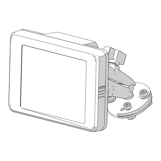
TPC TIREBOSS 2 Service Manual

TPC TIREBOSS 2 Service Manual

Tire pressure control

Advertisement

Quick Links

TIREBOSS 2
®
Tire Pressure Control
TB2 Service Manual
Version 2.0 | Current as of August, 2022
This is a working document that is
subject to change without notice
Contact TPC International with any inquries at;
15803-121A Ave., Edmonton, Alberta, Canada T5V 1B1
Toll Free Phone: North America 1-888-338-3587
|
New Zealand 1-800-443-971
Australia 1-800-148-694
|
Phone: (780) 451-4894
Fax: (780) 452-6786
Email: info@tirepressurecontrol.com
TECHNICAL - documents | DOCUMENTS | SERVICE MANUAL | Service Manual - V 2._

Advertisement

Table of Contents
loading
Need help?

Need help?

Do you have a question about the TIREBOSS 2 and is the answer not in the manual?

Questions and answers

Subscribe to Our Youtube Channel

Summary of Contents for TPC TIREBOSS 2

  • Page 1 Version 2.0 | Current as of August, 2022 This is a working document that is subject to change without notice Contact TPC International with any inquries at; 15803-121A Ave., Edmonton, Alberta, Canada T5V 1B1 Toll Free Phone: North America 1-888-338-3587...
  • Page 3: Table Of Contents

    Connecting OCU to Wifi ....................Adding a New Network to OCU ..............Connecting as ‘TPC-Tech’ ................Creating a ‘TPC-Tech’ Hotspot on IOS Devices ....... Creating a ‘TPC-Tech’ Hotspot on Android Devices ....Chapter 4 - Programming & Updates; Field OCU & SCU Replacements ................
  • Page 4 - Vehicle manufacturers safety instructions when this service procedure are current as of the date working on vehicles, indicated on the front cover. TPC International reserves the right to modify, revise, or discontinue - Vehicle manufacturers safety and best practice...
  • Page 5 AVOID direct high pressure wash TIREBOSS ® Important Information The TIREBOSS 2 system is a Tire Pressure Control System that monitors and controls tire pressures. - References to system components contained within this manual are as follows; OCU - Operator Control Unit...
  • Page 6: System Descriptions

    System Description INTRODUCTION The Tireboss 2 system is a second generation of the TIREBOSS® product, that provides the ability to change tire pressure in one or more groups of tires while the vehicle is in operation. The primary improvements in Tireboss 2 over the original Tireboss 1 system are: •...
  • Page 7 In addition to the system safety features outlined above, it should be noted that the TIREBOSS 2 systems use only quality components, such as DOT approved drive axle air hosing. The TPCS computer continously monitors tire pressure and controls the inflating, deflating, or maintaining of a preselected target tire pressure.
  • Page 8: Chapter 1 - System Schematics

    SECTION 1 SYSTEM SCHEMATICS...
  • Page 9: Truck Overview

    Service Manual Truck Overview Schematic Steer Axle Steer Axle Y-Fitting OCU Ignition Cable *Located in the truck cabin* Main Data Cable *TPC PN: 1000-420* Steer Axle Main Line SCU Power Cale *TPC PN: 1000-400* *Optional* TPC Wet Tank Control System *Optional* [SCU &...
  • Page 10: System Overview

    Tire Pressure Control Service Manual System Overview Schematic * Not required with newer * TIREBOSS 2 systems Switched Ignition Connect Red wire to ignition switched power inside cab. Connect Black wire to clean, strong ground in cab or on fire wall.
  • Page 11 Tire Pressure Control Service Manual...
  • Page 12 ATM-2 This page displays a high level schematic breakdown of the electrical system of your TIREBOSS 2 equipped truck. a further breakdown of each cable including appropraite voltage ranges per pin can be found on page 5-1 in the troubleshooting...
  • Page 13 Tire Pressure Control Service Manual Conventional Pneumatic Schematic Unloader Lines to compressor Air Dryer Primary Wet Tank Governor Secondary Wet Tank Truck Wet Tank...
  • Page 14 Tire Pressure Control Service Manual ADIS Dryer Pneumatic Schematic Unloader Line Feed from air Primary Compressor Wet Tank ADIS Dryer Secondary Wet Tank Wet Tank * *In ADIS systems, TPC Wet Tanks are an optional component with the PPV being remote mounted...
  • Page 15 Tire Pressure Control Service Manual Dual Dryer Pneumatic Schematic To Purge Tank Governor Primary Air Dryer Wet Tank Secondary Wet Tank Wet Tank...
  • Page 16 SECTION 2 ADJUSTMENTS, SETTINGS, & MAINTENANCE PROCEDURES...
  • Page 17 Tire Pressure Control Service Manual Tireboss 2 Service Inspection - Monthly Customer Name: Work Order #: Vehicle Make: TB2 Serial Number: Inspected by: Vehicle Mileage: Date: Unit #: Main Lines, Fittings & Attachments Comments Steer Wheel Hardware, Check; - Manual wheel valves for condition & operation ...
  • Page 18 Tire Pressure Control Service Manual Tireboss 2 Service Inspection - Annual Work Order #: Customer Name: Vehicle Make: TB2 Serial Number: Vehicle Mileage: Inspected by: Date: Unit #: System Operations Comments Correct operation of OCU ............... Low air supply warning at 75 (+/- 5) brake PSI ......
  • Page 19 Tire Pressure Control Service Manual Check trailer wheel hardware; - Manual wheel valves condition/ operation ......- Hoses and hardware condition ........... - Air flow check valve from each tire to valve ......- Tire pressure loss warning operation ........Use soapy water on all connections) ..
  • Page 20: Adjusting The Pressure Protection Valve [Ppv]

    Tire Pressure Control Service Manual Adjusting the Pressure Protection Valve [PPV] CONTAINED WITHIN THIS GUIDE ARE INSTRUCTIONS FOR SETTING THE FAILSAFE VALUES ON THE PRESSURE PROTECTION VALVE. FOR TRUCKS EQUIPPED WITH CONVENTIONAL DRYER SYSTEMS, FOLLOW THE STEPS BEGINNING ON PAGE 2-5 FOR TRUCKS EQUIPPED WITH AD-IS &...
  • Page 21 Tire Pressure Control Service Manual Conventional Dryer Equipped Trucks; 1. Locate the “Pressure Port” hose on the bottom of the VCU labeled “Press”. Using a 1/2” [13mm] box wrench, press on the outer ring of the brass fitting and remove the hose from the valve by pulling directly away from the fitting.
  • Page 22 Tire Pressure Control Service Manual AD-IS & AD-HF Dryer Equipped Trucks; 1. Locate the “Pressure Port” hose on the bottom of the VCU labeled “Press”. Using a 1/2” [13mm] box wrench, press on the outer ring of the brass fitting and remove the hose from the valve by pulling directly away from the fitting.
  • Page 23: Adjusting The Air Compressor Governor

    Tire Pressure Control Service Manual Adjusting the Air Compressor Governor CONTAINED WITHIN THIS GUIDE ARE INSTRUCTIONS FOR SETTING THE ON-BOARD AIR COMPRESSOR GOVERNOR FOR TRUCKS EQUIPPED WITH A SINGLE D2 GOVERNOR, FOLLOW THE STEPS BEGINNING ON PAGE 2-8 FOR TRUCKS EQUIPPED WITH A DUAL D2 GOVERNOR, FOLLOW THE STEPS BEGINNING ON PAGE 2-9 FOR TRUCKS EQUIPPED WITH A NON-ADJUSTABLE GOVERNORS,...
  • Page 24 Tire Pressure Control Service Manual For Trucks with a Single D2 Governor; *Note* Some trucks are equipped with governors that are non-adjustable and must be replaced with an adjustable governor before installing a TB2 control system. 1/4" Tee interupting brake sensor line and Pressure Protection Valve 1.
  • Page 25 Tire Pressure Control Service Manual e. Tighten the jam nut with a 7/16” [12mm] wrench once satisfied. f. Apply the trucks brakes to bleed the system down slowly until the air compressors “cut in” engages. Record the “cut in” pressure when the air compressor engages.
  • Page 26 Tire Pressure Control Service Manual d. Using the same flat-headed screwdriver, turn the set screw [COUNTER-CLOCKWISE to INCREASE the output air pressure, CLOCKWISE to DECREASE the output pressure]. *Note* Only turn the set screw a 1/4 turn at a time and keep track of how many turns are required.
  • Page 27: Rotary Union Maintenance

    [> 260 C] will suffice. Required Parts; - New Rotary Union [Refer to Parts Manual for TPC Part #] - Nemco Red Max EP1.5 Tacky Grease - Loctite 5452 - Brake Cleaner Required Tools;...
  • Page 28 Tire Pressure Control Service Manual Rotary unions should be checked weekly for excessive wear to ensure proper operation of the system. A faulty/ damaged rotary union will introduce a leak into the system that will result in the deflation of an entire tire group when the system is left unpowered [I.e. when the trucked is parked and turned off].
  • Page 29 Tighten until these fittings are oriented in the same position. 6. Using the bent 15/16” TPC wrench [TPC Part # 392- 7606], or a 15/16” crowfoot with 6” extension and ratchet, remove the old rotary union and copper washer.
  • Page 30 7. Inspect the hole the rotary union came from and remove any foreign debris and clean before continuing. 8. Install the new copper washer [TPC Part #1105-070] onto the new rotary union before installing it into the wheel end valve plate.
  • Page 31 Tire Pressure Control Service Manual Wheel End Valve [WEV] Service Procedure The wheel end plates are exposed to the environment and require yearly servicing to ensure correct operation. The following procedure outlines the process of this service. Before beginning the service; - Ensure the truck is parked on a flat surface with the parking break on before beginning service - Ensure the Valve Control Unit (VCU) is relieved of air pressure...
  • Page 32 Tire Pressure Control Service Manual 1. Ensure that the truck is parked on a level surface with the parking break engaged prior to beginning the service. 2. Begin by checking the rotary unions for excessive wear or leaks. Spray a light coat of soapy water over the entire WEV plate.
  • Page 33 17. Repeat steps 1-16 for all other tires 18. Open the wheel end valves and leak check with a soap and water mixture. 19. Turn on the TIREBOSS 2 system and set it to its highest setting before leak testing again. 2-17...
  • Page 34: Valve Rebuild Procedure

    Tire Pressure Control Service Manual VALVE REBUILD PROCEDURE STILL UNDER CONSTRUCTION 2-18...
  • Page 35 Tire Pressure Control Service Manual VALVE REBUILD PROCEDURE STILL UNDER CONSTRUCTION 2-19...
  • Page 36 SECTION 3 OCU OPERATIONS...
  • Page 37 Tire Pressure Control Service Manual OCU Operation Screens The following diagrams have been included to assist in navigating the OCU menu screens. While only the Main Screen will be used during day-to-day operation, the various other screens installed onto the unit will be required for various updating, diagnostic and trouble shooting procedures.
  • Page 38 Tire Pressure Control Service Manual System Status Menu Ref. Purpose Access System Information Screen System Status Button Valve Status Button Valve Load Status Button Heater Status Button GPS Information Button Return to Main Screen Return to Previous Screen Help Button Settings Menu Screen Ref.
  • Page 39: Selecting Applications

    Selecting Applications The following steps describe the process of changing between different applications created for and installed onto your TIREBOSS 2 system. 1. From the Main Screen, navigate to the Initial Menu Screen. 2. From the Initial Menu Screen, navigate to the Application Select Screen.
  • Page 40 Tire Pressure Control Service Manual 5. Selecting the Enable/ Disable Application button will automatically trigger a security screen asking for the user password. 6. Enter the user password followed by selecting the “unlock” button in the screens bottom left corner. *NOTE* User password is 15803 7.
  • Page 41 Service Manual New Configuration Download The following steps describe the process of downloading configurations already installed onto your TIREBOSS 2 system. 1. From the Main Screen, navigate to the Initial Menu Screen. 2. From the Initial Menu Screen, navigate to the Settings Menu Screen.
  • Page 42: Connecting Ocu To Wifi

    Connecting OCU to WiFi The following steps describe the process that must be followed in order to effectively connect the OCU of your TIREBOSS 2 system to a WiFi network. 1. From the Main Screen, navigate to the Initial Menu Screen.
  • Page 43: Adding A New Network To Ocu

    Service Manual Adding a New Network to OCU *NOTE* The TIREBOSS 2 system can only be connected to EITHER a password protected or open network. In other words, public networks that require internet authentication [I.e. McDonald’s free WiFi] are not able to be used for this task.
  • Page 44: Creating A 'Tpc-Tech' Hotspot On Ios Devices

    In order to rename the network name you must change the name of your phone to replicate the ‘TPC-Tech’ name. This can be done with the following process; 1. Open the ‘Settings’ application on your I-Phone or cellular connected Apple device.
  • Page 45 SECTION 4 SYSTEM PROGRAMMING & UPDATES...
  • Page 46 Tire Pressure Control Service Manual Field Replacement of OCU The following steps outline the process required to replace an OCU in a previously installed and functioning system. 1. Ensure the system is powered off and the system main fuse is removed prior to beginning replacment.
  • Page 47: Firmware/ Software Updates

    The following steps describe the process that must be followed in order to update either the Firmware or Software Version of your TIREBOSS 2 System. 1. Verify that you are in a location where a reliable WiFi network can be accessed.
  • Page 48 SECTION 5 TROUBLE SHOOTING GUIDE...
  • Page 49: Wiring Pinout

    Tire Pressure Control Service Manual WIRING PIN OUT CABLE 1000-120 OCU POWER CABLE 2 Amp Push in Style Mini Fuse Holder Black Detail A Detail B Detail A - Battery Hook-Up Detail B - Black, 6 Pin, OCU Connector Red Wire - 22 AWG | Red | Switched Power [+] Pin 1 - 22 AWG | Black | Ground [-] Black Wire - 22 AWG | Black | Ground [-] Pin 2 - N/A...
  • Page 50 Tire Pressure Control Service Manual WIRING PINOUT CABLE 1000-400 SYSTEM POWER Detail A Orange Black 15 Amp Push in Style Fuse White Detail B Detail C Detail A - Battery Hookup Detail C - Grey, 12 Pin, Duetsch Connector Orange Wire - 14 AWG | Battery [+] Pin 1 - N/A Black Wire - 14 AWG | Ground [-] Pin 2 - N/A...
  • Page 51 Tire Pressure Control Service Manual WIRING PINOUT CABLE 1000-420 SYSTEM I/F CABLE Black Detail A Detail B Detail C Detail D Detail A - Black, 8 Pin, OCU Connector Detail C - Remote Alarm Hookup Pin 1 - 20 AWG | Black | OCU RX [-] Red Wire - 18 AWG | Remote Alarm [+] Pin 2 - 20 AWG | White | OCU RX [+] Black Wire - 18 AWG | Remote Alarm [-]...
  • Page 52 Tire Pressure Control Service Manual WIRING PINOUT CABLE 1000-440 VCU - VCU I/F CABLE Detail A Detail A - Grey, 8 Pin, Duetsch Connector Pin 1 - 14 AWG | White | Heater [+] Pin 2 - 14 AWG | Black | Heater [-] Pin 3 - 14 AWG | Yellow | LIN BUS Pin 4 - 16 AWG | Orange | Battery Power [+] Pin 5 - 16 AWG | Black | Ground [-]...
  • Page 53 Tire Pressure Control Service Manual CONNECTOR PINOUT CABLE 1000-440 PORT C VCU - VCU I/F CABLE Detail A PORT C on SCU HOUSING - 12 Pin Note: Pin 1 - 20 AWG | Red | OCU RX [+] 0v. - 5v. signal between pins 1&12 Pin 2 - 20 AWG | Black | OCU TX [-] 0v.
  • Page 54 2. Perform a vehicle walk around and check for leaks in the trucks air supply system between the Repair leaks if found compressor and the TIREBOSS 2 Truck air supply pressure protection valve [PPV] Low break air pressure falls pressure below ‘low air...
  • Page 55 Tire Pressure Control Service Manual CODE MESSAGE TRIGGER TROUBLE SHOOTING REPAIR NUMBER TEXT CONDITION PROCEDUE 1a. Plug in ‘SCU Alive Diagnostics Plug’ and follow instructions on page __. If you do not have access to a ‘SCU Alive Diagnostic Check battery connections OCU cannot Plug’, using a voltmeter confirm for excessive and/or damage...
  • Page 56 Tire Pressure Control Service Manual CODE MESSAGE TRIGGER TROUBLE SHOOTING REPAIR NUMBER TEXT CONDITION PROCEDUE Air is flowing through the VCU; indicatates that there is a mechanical issue that requires repair. Pull cartridges, inspect for debris, and clean/ replace as 2.
  • Page 57 Configuration data on either configurations can be found on page 3-5 data faulty OCU or SCU Version Error OCU and SCU Ensure OCU is connected to Wifi and contact TPC international for 1013 System not firmware firmware upgrades. operational incompatable...
  • Page 58 1.4. 1. Using the system information screen on the OCU confirm Clean battery contacts/ supply voltage to TIREBOSS 2 charge truck battery system [should be between 9 - 36v.] SCU supply Power Error 2.
  • Page 59 (furthest forward = VCU main board. lowest value) 3. Contact TPC international 1. Verify communications cables between SCU and VCU have clean Clean / Repair as required connections and are in tact. 2. Verify correct sequencing of Ensure communication valves by referring to "VCU...
  • Page 60 1. Re-download problem configuration by following sequence Config. Error data explained on page 3-5 1044 System not incompatible operational between OCU & 2. Contact TPC International valve heater hardware Heater power 1045 incompatible Contact TPC International out of range with VCU...
  • Page 61 2. Power down the SCU by removing the main system fuse and 2006 target pressure Loaded wait 30 sec. before reinstalling and powering up the system Target 3. Contact TPC International VCU detects Self Test 2009 internal failure Contact TPC International...
  • Page 62 2010 Pressure reading invalid found on Load sense status screen sensor error pressure values 2. Contact TPC International 1. Ensure that codes 1011 and/ or Diagnosis and Repair before 1044 are not present in the OCU returning Alarm status screen If arrow not present;...
  • Page 63 2. If alarm 3003 is the only active alarm recorded, pull the main fuse 3003 Transient Error between OCU and wait 30 sec. before rebooting. and VCU 3. If problem persists, Contact TPC International VCU receives an invalid pressure Invalid pressure 3004 Contact TPC International...
  • Page 64 3. Check VCU internals for debris Clean / Replace as required defaltes and/ or blockages 4. Repalce VCU main board 5. Replace entire VCU 6. Contact TPC International OCU Cannot 1. On the alarm status screen, communicate Diagnosis and Repair before OCU fails to...
  • Page 65 1. On the OCU alarm status screen, Diagnosis and Repair before ensure a 1041 error is not present returning GPS Signal has 3024 GPS Lock Lost been lost 2. Power off the OCU. Wait 30 sec. before restarting 3. Contact TPC International 5-17...
  • Page 66: Ocu Diagnostic Lights

    Tire Pressure Control Service Manual OCU Diagnostic Lights The OCU diagnostics lights are located on the main circuit board of the unit. Thus, a partial disassembly of the OCU unit must be performed in order to access the lights. Disassembling the OCU; 1.
  • Page 67 Tire Pressure Control Service Manual The DL1 LED indicates the state of the power control processor U5. Flash lengths are; Long Flash, ~1 s. | Short Flash ~0.2s DL1 (Blue) LED Description IGN power off, all OCU supplies off OFF (Continous) IGN power on, all OCU supplies on, SOM providing heartbeat 1 long off, long off signal.
  • Page 68: Scu Alive Diagnostic Plug

    These plug are proprietary to the TIREBOSS 2 system and are not usually supplied for individual systems. If you maintain a large fleet of TIREBOSS 2 equipped trucks and are in need of these tools, please contact TPC International to discuss procuring these devices.
  • Page 69: Scu Diagnostic Plug

    Pin 3 Low power mode/ No status within Section 3-A | Page 5-24 [White LED] power within system the TIREBOSS 2 system Fast System power is out of Section 3-B | Page 5-24 Flash range 5-21...
  • Page 70 Tire Pressure Control Service Manual Light Light Purpose Repair/ Locations to check Location Activity Meaning/ Status Active LIN bus communication This light is used Low power mode/ LIN to indicate the Section 4-A | Page 5-24 communication is idle Pin 4 status of LIN bus [Yellow communications...
  • Page 71 Tire Pressure Control Service Manual SCU Diagnostic Plug Procedures Section 1-A | Green LED Off If the Green LED is off (along with all other Diagnostic LEDs) when the system should be in Full Power Mode, check the supply voltage to the system (Pins 5&8 and 6&7 on the grey connector in the SCU).
  • Page 72 Tire Pressure Control Service Manual Section 2-C | Orange LED Fast Flash Check the OCU Alarm Status screen for one or more ‘2001 Heater Current errors’ and troubleshoot according to the process outlined on page 5-13. This indicator only serves as a quick visual status of VCU heater operation and provides no other information.
  • Page 73 If they look correct, restart the datalogger and power cycle the SCU. If this does not resolve the problem it is likely either an SCU failure or a cable problem. This problem may require engineering support to resolve, contact TPC International for assistance. 5-25...

This manual is also suitable for:

Tb2

Table of Contents