
Subscribe to Our Youtube Channel
Related Manuals for GW Instek AFG-125

Summary of Contents for GW Instek AFG-125
- Page 1 Arbitrary Function Generator Module AFG-125 / 225 / 125P / 225P QUICK START GUIDE GW INSTEK PART NO. 82DS-23045MB1 ISO-9001 CERTIFIED MANUFACTURER...
- Page 2 This manual contains proprietary information, which is protected by copyright. All rights are reserved. No part of this manual may be photocopied, reproduced or translated to another language without prior written consent of Good Will Corporation. The information in this manual was correct at the time of printing.
- Page 3 125/225/125P/225P. See the user manual for further details. The AFG-125P & 225P also incorporate a power supply output with a selectable voltage output of 2.5, 3.3 or 5V. The AFG-125/225/125P/225P are only supported with GDS-2000A series DSOs with firmware version V1.19 or above installed. Main Features Sine, Square, Ramp, Pulse, Noise, •...
-
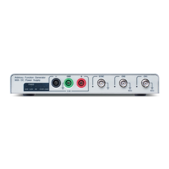
Page 4: Front And Rear Panel
Front & Rear Panel Front Power Supply Status LEDs SYNC Output CH1 Output WP V V V Negative Output Positive Output CH2 Output Indicates the state of the power Power Supply supply (AFG-125P/225P only). -
Page 5: Installation
Installation AFG APP Installation The AFG-125/225 modules require a separate APP installation. Load the AFG.gz APP file onto a USB flash drive. Insert the USB flash drive into the USB slot on the front panel. Press > File Utilities. Select the AFG.gz Utility file on the USB flash drive. - Page 6 Installing the AFG-125/225 Module The AFG-125/225 modules are installed into the area that is left between both of the DS2-FH1 housings. Slide the module into the slot that was created between the DS2-FH1 housings. The front of the module should be facing forwards.
- Page 7 The module can now be slid out from the housing. USB Configuration The USB Device port needs to be configured to provide power for the AFG-125/225 if an external power supply is not used. As shown previously in the “Installing the AFG- 125/225 Module” section, connect the GTL-254 USB cable.
- Page 8 Accessing the Arbitrary Function Generator Like all options, the AFG-125/225 options can be accessed with the Option key. O Press the key and select AFG. The AFG-125/225 is now ready to be used. Basic Waveform Selection The AFG-125/225 options have five selectable basic waveforms.
- Page 9 ARB Waveform The following will describe how to create and output an arbitrary waveform. Select the output channel by pressing Signal 1 Setup or Signal 2 Setup. Press ARB from the bottom menu. Press ARB on the side menu and toggle ARB On. Press Edit.
- Page 10 Modulation The following will describe how to modulate a carrier waveform (shape) with the basic waveform shown previously. Select a basic waveform as shown previously. This will be used as the modulating (baseband) signal. Press MOD from the bottom menu. Press MOD on the side menu and toggle MOD On.
- Page 11 Burst Modulation The following will describe how to create a burst waveform. Press Burst from the bottom menu. Press Burst on the side menu and toggle Burst On. Press N Cycle set the burst parameters. Choose Infinite for an infinite number of burst cycles or press Cycle to set the number of burst cycles for each period.
- Page 12 To toggle the load impedance between 50Ω and High Z, press Load. For basic waveforms, press Phase to set the output phase. On dual channel models, both output channels can be phase-synchronized by pressing the S_Phase soft-key. State Display The State Display function gives an overview of the arbitrary function generator settings for both channels.
- Page 13 Dual Channel (AFG-225/225P only) The following will describe the basic 2 channel functions. Ensure both channels have already been turned on in the Signal 1 Setup/ Signal 2 Setup menus. Press UTIL > Dual Chan from the first level of the AFG menu level.
- Page 14 Press UTIL > Sync Setup from the first level of the AFG menu level. Press Sync and toggle Sync on. Press Source and choose Signal 1 or Signal 2 as the source signal to follow. Press Mode and select the SYNC signal mode: ...
Need help?
Do you have a question about the AFG-125 and is the answer not in the manual?
Questions and answers