Advertisement
The fl ashing Christmas tree kit is made up of three circuit boards. Assemble and solder so that 36 clear LEDs fl ash
multiple colors alternately, presenting the three-dimensional outline of the Christmas tree (better viewing at night).
Please be sure to read all of the steps in the manual thoroughly before starting the assembly of the Christmas Tree Kit.
Assembly process:
1.) Soldering Christmas Tree circuit board (abbreviated as Board A). Identify A by fi nding the "2PH88566A" or the
Tree with the slot starting from the top. Match the color code on the pictures with the correct resistors.
a.) Solder Brown, black, orange 10K resistors (R1 R3 R5 R7)
b.) Solder a Red, Black, Red resistor to R2, a Brown, Black Red to R4, and an Orange, Orange, Brown resistor
to R6.
3D Color Changing LED Christmas Tree Kit
Assembly Instructions
1
Advertisement
Table of Contents

Summary of Contents for Parts Express 320-291
- Page 1 3D Color Changing LED Christmas Tree Kit Assembly Instructions The fl ashing Christmas tree kit is made up of three circuit boards. Assemble and solder so that 36 clear LEDs fl ash multiple colors alternately, presenting the three-dimensional outline of the Christmas tree (better viewing at night). Please be sure to read all of the steps in the manual thoroughly before starting the assembly of the Christmas Tree Kit. Assembly process: 1.) Soldering Christmas Tree circuit board (abbreviated as Board A). Identify A by fi nding the “2PH88566A” or the Tree with the slot starting from the top. Match the color code on the pictures with the correct resistors. a.) Solder Brown, black, orange 10K resistors (R1 R3 R5 R7) b.) Solder a Red, Black, Red resistor to R2, a Brown, Black Red to R4, and an Orange, Orange, Brown resistor to R6.
- Page 2 c.) Solder 3 transistors, bending the components before soldering (otherwise they won’t be able to lay flush if soldered first). Make sure to match the shape of the transistors to the shape printed on the board. d.) Solder 3 +47uF electrolytic capacitors (bending the components before soldering, otherwise, they won’t be able to lay flush if soldered first). Make sure to match the shape to the printed shape on the board. The long terminal is positive, the short terminal is negative. i.) First estimate the capacitor pin from which position to do 90 ° bend ii.) After folding the pin, insert it into the corresponding hole (pay attention to the installation direction, matching the shape of the board). iii.) Bend the capacitor pin 90° in the correct direction and then solder it...
- Page 3 e.) Soldering LED lights (matching the shape of the board), numbered D1~D18. (The square pad of circuit board is positive, and the long pin of LED is positive i.) First estimate the LED pin from which position to do 90° bending ii.) After folding the pin, insert it into the corresponding hole (pay attention to the installation direction) iii.) Bend the LED pin 90° in the correct direction and then solder it The soldering of Board A is completed.
- Page 4 2.) Next, use the same direction to solder the B circuit board, referred to as Board B. There are two different installation positions of components for the Board A and B (just install according to the location on the component list) a.) R2 is orange, orange, brown, R4 is red, black, red and R6 is brown, black, red. The remaining resistors’ locations are brown, black, orange (R1, R3, R5). b.) Solder transistors, capacitors and LEDs like board A. c.) After Board A and Board B are soldered, you can power on to test whether the two boards can glow and flicker normally. After both A and B flash normally, continue with the following steps. Board A Board B (After boards A and B are soldered, connect to a voltage of about 4.5V respectively, confirm that all the LED lights can flash normally, and then continue the following steps)
- Page 5 3.) Soldering CTR-30C circuit board, referred to as Board C a.) Soldering 1 DC socket (matching the shape of the board) b.) After the DC socket is soldered, the pins need to be cut as short as possible to prevent affecting the installation of the battery box behind. (Reinforce the DC socket with the cut component pins) in a “U” shape if you plan on using it instead of batteries. c.) Soldering 1 key switch with the notch facing out. If you cannot find the notch, click the push button to make the switch pop up. Switch notch outward...
- Page 6 d.) Combination of board A and Board B (with direction, positioning the arrows of the two boards are as shown below) after the two positioning arrows are aligned, solder the two boards together with a soldering iron i.) Align the two positioning arrows first ii.) Solder the two boards with tin wire iii.) The positioning arrows of board A and board B are shown in the enlarged picture on the upper left e.) Combination of the battery box and Board C i.) Pass the battery box wire out of the bottom of board C according to the corresponding polarity ii.) Reserve a certain length of wire, cut off the excess wire iii.) Solder the battery box wire -- matching + red, - black iv.) Combine the battery box with screws and nuts...
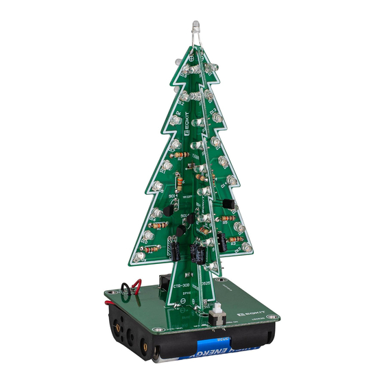
- Page 7 5.) Combination of the pre-assembled Board A and B to Board C positioning the power polarity correctly with positive over positive like shown below 6.) Solder the top one LED long lead + with square solder joint Now your Christmas Tree is complete, the finished picture is as follows:...
- Page 8 Two power supply methods: Power indicator 1.) 3 AA batteries (sold separately) 2.) External 5 VDC USB-A power supply/port (sold separately) External 5V power supply Power switch 3 AA batteries Specifications: Working voltage: DC4.5-5V Power supply: 3 AA batteries or 5 VDC USB power Dimension: 2.36” x 2.36” x 5.35” (60mm*60mm*136mm) Last Revised: 11/1/2021 © Parts Express ®...
Need help?
Do you have a question about the 320-291 and is the answer not in the manual?
Questions and answers