Table of Contents
Advertisement
Quick Links
Advertisement
Table of Contents

Summary of Contents for Harrison 42000005
- Page 1 ELECTROSURGERY ANALIZER User Guide.
-
Page 3: Table Of Contents
Table of Contents INTRODUCTION ---------------------------------------------------- 4 SAFETY INFORMATION ------------------------------------------ 4 ACRONYMS AND DEFINITIONS -------------------------------- 5 PACKAGING --------------------------------------------------------- 6 UNDERSTANDING THE DEVICE ------------------------------- 7 TURNING ON THE DEVICE ------------------------------------- 10 TEST MODULES ---------------------------------------------------13 GENERATOR OUTPUT TEST ----------------- 13 EXTERNAL RESISTANCE MODULE --------- 14 CQM ------------------------------------------------- 20 HF LEAKAGE CURRENT ----------------------- 21 SOFTWARE AND APPLICATION ------------------------------- 29... -
Page 4: Introduction
INTRODUCTION HARRISON Electrosurgery Analyzer is practical, compact, portable, and easy to handle. It is used in electronic scalpel performance tests. Harrison allows the simulation of: Power Current Crest Main Factor Frequency Th e d a ta H ARR I SO N co ll e c t s pr o vi d es a b ette r an a l ys i s o f d iff e ren t e l e c t ro s ur g ic a l u n it s in d iffe re n t te st mo da l i ti e s. -
Page 5: Acronyms And Definitions
Do not expose the device to high humidity. Do not expose the device to temperatures above 50 °C. Respect the device’s battery life. Insert the connectors only into the spots intended for operation. Do not connect this device to the patient. Replace the power cord if any damage is identified Replace accessories if any damage is identified. -
Page 6: Packaging
PACKAGE CONTENT Harrison analyzer comes with the following items: 1 x Harrison (PN 42000005) 1 x User Manual (PN 12000034) 1 x Calibration Certificate Accessories 2 x 30 cm Banana/banana connector (PN 31000001) 4 x 110° banana/banana connector (PN 31000024) -
Page 7: Understanding The Device
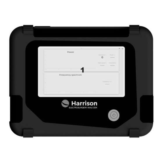
UNDERSTANDING THE DEVICE Next, the device will be demonstrated with the description of its connectors and controls VISTA FRONTAL: Touch Screen. On/Off Button. - Page 8 VISTA SUPERIOR: Cable Connector with Fuse Scalpel Input - Active. Holder. Internal Load Connector Scalpel Inlet - Passive. (default 200ohm). External Load Connector. Ground Pin. Air Circulation. VISTA LATERAL ESQUERDA VISTA LATERAL ESQUERDA External Module Connection External Module Connection...
- Page 9 VISTA LATERAL DIREITA Air circulation. VISTA TRASEIRA Serial number identifi cation tag.
-
Page 10: Turning On The Device
TURNING ON THE DEVICE Press the “on/off” button to turn on the device. The device will perform internal communication tests and display the settings screen of each module to be tested. SCREEN Dragging the screen downwards, we have access to the menu with options: Bluetooth Wifi... - Page 11 Bluetooth: allows connection to the cell phone and integration with the Arkmeds Software management system. Wifi: enables the device to be connected to the internet network to aid in remote access by the factory. By clicking on the icon, a list of available networks will appear.
- Page 12 Card 1: with only this option enabled, it is possible to view the Power reading module in full screen. Card 2: with only this option enabled, it is possible to view the frequency reading module in full screen. Note: with 2 Cards enabled, both modules will be displayed.
-
Page 13: Test Modules
TEST MODUL E S In this section are each of the features of HARRISON Electrosurgery Analyzer. ESU TEST HARRISON measures the performance of high-frequency electrosurgical units (ESU). The product makes measurements and tests: 1. Generator Output Test 1.1 Power, RMS 1.2 Current, RMS... -
Page 14: External Resistance Module
- 3 resistors of 100R (R1 to R3); - 2 of 200R (R4 and R5). Harrison’s External Resistance module allows tests with different resistance values in front of resistor associations. Cables are sent along with the module to make connections to fulfill Monopolar, Bipolar, and CQM tests. - Page 15 In addition, it has a heat dissipation system. To activate it, simply connect the cable to the left side of Harrison and the External Resistance Module panel.
- Page 16 MONOPOLAR The following figure shows the connection for the test between the ESU and Harrison. Make the connections to perform the power test as follows: 1. Connect the active pen connector on the ESU to the Active port on HARRISON.
- Page 17 Harrison Settings In HARRISON, click on the “Resistance” fi eld and indicate the resistance value adopted in the test. A bar to adjust the resistance value and an icon to perform the input by a numeric keypad will be displayed.
- Page 18 Generator Output Test - Cut and Coagulation Connections: BIPOLAR The following figure shows the connection for the test between the ESU and Harrison. Make the connections to perform the power test, as follows: 1. Connect the two ESU bipolar connectors to HARRISON’s Active and Passive port.
- Page 19 Harrison Settings In HARRISON, click on the “Resistance” fi eld and indicate the resistance value adopted in the test. A bar will be displayed to adjust the resistance value, and an icon to perform the input by a numeric keypad.
-
Page 20: Cqm
Contact Quality Monitor (CQM) Test Connections The following figure shows the connection for the test between the ESU and Harrison’s resistance module. Make the connections to perform the contact quality test as follows: 1. Connect the Split board terminals to the target resistance value. -
Page 21: Hf Leakage Current
HF Leakage Current Test Test 1 – CF-Type Leakage Current Shows the total open circuit high-frequency current leakage from a single electrode (active and passive) isolated to ground through a 200- ohm resistive test load. - Page 22 1. Connect a 200-ohm resistor (A4 to A6 and A5 to A7) to the external resistor input (A4 and A5). 2. Connect the active part of the ESU (B1) to Harrison’s active terminal (A2). 3. Interconnect the ground pin (A1) with the passive connector (A3) and the ESU ground.
- Page 23 CF-Type Leakage Current - Active and Passive Part...
- Page 24 Harrison Settings In HARRISON, click on the “Resistance” field and enter the resistance value of 200 ohms. A bar for adjusting the resistance value and an icon for entering it using a numeric keypad will be displayed. Reading: : with the connections made and adjusting the resistance value set, the leakage current value in RMS will be shown on the screen.
- Page 25 ESU and HARRISON. Make the connections to perform the BF- type leakage current test as follows: 1. Connect the dispersive part of the ESU (B2) to Harrison’s active connector (A2). 2. Connect the active part of the ESU (B1) to the A7.
- Page 26 BF-Type Leakage Current...
- Page 28 Harrison Settings In HARRISON, click on the “Resistance” field and enter the resistance value of 200 ohms. A bar for adjusting the resistance value and an icon for entering it using a numeric keypad will be displayed. Reading: with the connections made and adjusting the resistance value set, the leakage current value in RMS will be shown on the screen.
-
Page 29: Software And Application
1. Connect the dispersive part of the ESU (B2) to Harrison’s active connector (A2). 2. Connect the active part of the ESU (B1) to the A6. 3. Connect a 200-ohm resistor from the external module R4 or R5 (C1 to A4 and C2 to A5) to the external resistor port (A4 and A5). -
Page 30: Problems And Solutions
PROBLEMS AND SOLUTIONS DEFECT POSSIBLE CAUSE SOLUTION Connect the device to the Off-grid device and power grid and check if it low battery starts up. The device does not turn on Replace the fuse. If it does not turn on, please Blown Fuse contact Arkmeds authori - zed Service Provider. -
Page 31: Battery Indicator
BATTE RY In Harrison, the battery level indicator is displayed in the upper right. Status Symbol Empty Half load Full Connected to the power grid TECHNICAL SPECIFICATIONS GENERAL Operating 10 °C to 40 °C (50 °F to 104 °F) Temperature Storage Temperature -20 °C to +60 °C (-4 °F to +140 °F) - Page 32 POWER Range 1.0 - 400 Watts RMS Resolution 0.1 Watt Variation ± 5% reading CURRENT Range 0 to 20000 mA Resolution 0.1 mA Variation ± 5% reading CREST FACTOR Range 1 to 999.9 Variation ± 1% FREQUENCY Range 1kHz to 20Mhz INTERNAL RESISTANCE Balance 200Ω...
-
Page 33: Faq
FA Q In case of doubts, problems, or suggestions, please contact the Arkmeds Customer Success Team at: https://www.arkmeds.us/support evolving people, companies, and markets. E L E C T R O S U R G E RY A N A LY Z E R...
Need help?
Do you have a question about the 42000005 and is the answer not in the manual?
Questions and answers