
Subscribe to Our Youtube Channel
Summary of Contents for Aircare VariPhase
- Page 1 AirCare VariPhase™ User Manual Variphase Variphase HP ACV1xxx Family of MODBUS® Equipped Speed Controls for Fans and Blowers 2-14 Amperes www.aircareautomation.com...
-
Page 2: Table Of Contents
Installation........................19 Hall Sensor for Speed Sensing and Regulation ..............19 Frequently Asked Questions ..................19 AirCare Console™ and AirCare Variphase™ are trademarks of AirCare Automation Inc. MODBUS® is a registered trademark of Schneider Automation Revision 1.1 Variphase User Manual... -
Page 3: Product Overview
Optional covers provide NEMA1 level protection for all ratings. Variphase HP has four sets of power terminals to simplify connection to up to four motors. In this configuration all four motors will be supplied with the same voltage and run at the same speed. -
Page 4: Part Numbers And Ratings
Part Numbers and Ratings AirCare’s Variphase line-up consists of 11 base part numbers covering ratings from 115V 1.7A to 277V 14A. Input / Max Output Voltage Input/Output Ambient 115Vac 230Vac 277Vac Current at (max) +/- 15% +/- 15% +/- 15% 25°... -
Page 5: Safety
Where the control is approved as a recognized component, it is for use only in complete • equipment where the acceptability of the combination is determined by an approved testing agency. Revision 1.1 Variphase User Manual Page 5... -
Page 6: Compliance
Compliance AirCare Variphase products carry the following safety approvals. Model numbers not listed below are not presently agency approved. Recognized Component UL508c Power Conversion Equipment CAN/CSA C22.2 No. 14-M91. UL File number E241590. ACV1021 ACV1022 ACV1033 ACV1041 ACV1042 UL Listed Device UL508c Power Conversion Equipment CAN/CSA C22.2 No. -
Page 7: Installation
For large systems, we recommend testing small sub-systems before completing full-scale installation. In some systems additional RS485 devices may be needed to resolve offsets in ground voltage and ambient noise. For large installations, consult AirCare Automation for advice on RS485 network configuration. Revision 1.1... -
Page 8: General Operation
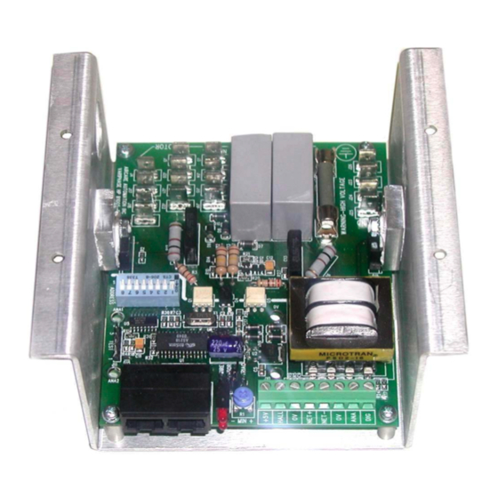
L-Bracket RS485 Network Ports LED Indicators Option Jumpers Control Terminals Power and Motor Connections Address Switches Figure 1 Variphase HP Features Power and Motor Connections Figure 2 Heatsink Address Switches Option Jumpers Control Terminals RS485 Network Ports Minimum Speed Pot LED Indicators Revision 1.1... -
Page 9: Control Mode Overview
Speed regulation modes use an external Hall-effect sensor to provide a speed feedback signal from the motor. In this mode, Variphase will hold motor speed constant, even under varying load conditions. In networked mode it also allows the speed to be set in RPM units. -
Page 10: Address Dip Switches
Address DIP Switches Each Variphase in a network must be set to a unique address between 1 and 127. There are 8 switches on the DIP switch block of which switch 1-7 are used for addressing. Switch 8 should be left in the OFF position (not used for addressing). -
Page 11: Analog Input Closed-Loop Control
Analog Input Closed-Loop Control Overview An external potentiometer controls set-point from 0% to 100%. • Variphase automatically adjusts motor output to maintain set-point • P, I and D parameters can be adjusted to configure closed-loop response • Adjust Minimum Speed Pot to limit lowest motor voltage. -
Page 12: Analog Speed Control With Speed Regulation
An external potentiometer controls set-point from 0% to 100%. • 100% motor speed is set using Modbus Reg 13 (default is 1500 rpm) • Variphase automatically adjusts motor output to maintain set-speed • P, I and D parameters can be adjusted to configure closed-loop response •... -
Page 13: Led Indicators
Led is on steadily. In addition, anytime the control responds to a Modbus message the Led flickers briefly. Diagnosing Other Faults Most Variphase models have an internal fuse. Excessive load current will cause the fuse to fault and the unit will be non-functional and non-responsive to network communications. The fuse is NOT field replaceable. -
Page 14: Power Wiring For Variphase 2-8 Amp Models
Power Wiring for Variphase 2-8 Amp Models 3 wire motor connection Use this diagram with PSC motors for optimal efficiency and lowest noise. Aux Winding Common Line From AC Main Winding Line Neutral Motor Figure 6 Revision 1.1 Variphase User Manual... - Page 15 Power Wiring Diagram – 2 wire Motor Connection Common Line From AC Main Line Neutral Motor Figure 7 Revision 1.1 Variphase User Manual Page 15...
-
Page 16: Power Wiring For Variphase Hp Models
Power Wiring for Variphase HP Models 3 wire motor connection Use this diagram with PSC motors for optimal efficiency and lowest noise. Aux Winding Common Neutral From AC Main Line Line Motor Figure 8 Revision 1.1 Variphase User Manual Page 16... -
Page 17: Network Communications
Network Communications Building a network of Variphase Controls is easy: Daisy-chain units together using standard RJ-45 patch cables (available from AirCare) • Configure each unit to a unique address • Add an AirCare Console and apply power • Set To Address 1... -
Page 18: Register Definition Summary
Register Definition Summary These definitions are provided for background information only. When using AirCare Consoles, there is normally no need to access Variphase Modbus registers. Register Function Type Motor Start/Stop Motor Speed (0-100%) P Value I Value D Value Motor Speed (RPM) -
Page 19: Installation
This can normally be achieved by mounting Variphase in a suitable enclosure and locating it so it will not be affected by condensation. The mounting position and method must also meet UL508c requirements for electrical spacings.
Need help?
Do you have a question about the VariPhase and is the answer not in the manual?
Questions and answers