Advertisement
Available languages
Available languages
Advertisement
Table of Contents

Related Manuals for Elenberg FS-4016


Summary of Contents for Elenberg FS-4016
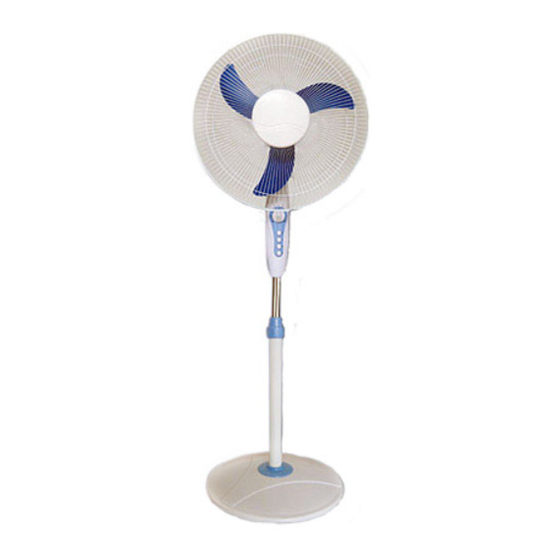
- Page 1 НАПОЛЬНЫЙ ВЕНТИЛЯТОР FS-4016 РУКОВОДСТВО ПОЛЬЗОВАТЕЛЯ...
-
Page 2: Важная Информация
ЭКСПЛУАТАЦИЯ 1. Будьте внимательны, когда собираете или разбираете прибор, не применяйте чрезмерных усилий, соединяя отдельные части прибора. Для сборки и разборки прибора достаточно иметь только два инструмента: отвертку и пассатижи. 2. Устанавливайте вентилятор в сухом месте. 3. Регулярно протирайте прибор влажной тканью. 4. - Page 3 СБОРКА Единственный инструмент, который пона- добится для сборки - это отвертка. 1. Подставка Снимите 4 винта с планок подставки. Совместите планки А и Б крест на крест. Проверьте, совместились ли крепежные отверстия с отверстиями фланца. Вставьте внешнюю трубку в скрещенные планки...
- Page 4 внешнем пластиковом кольце. b. Защелкните два крепежных элемента. 2) Прикрепите пластину с лейблом на переднюю решетку. ВНИМАНИЕ Не включайте вентилятор с повреж- денным или деформированным пропеллером. СПОСОБ ИСПОЛЬЗОВАНИЯ 1. Переключение скоростей Чтобы включить вентилятор и задать скорость, нажмите одну из кнопок: 1,2,3. Чтобы выключить вентилятор...
- Page 5 По истечении срока службы товара, необходимо обратиться в сервисный центр за консультацией по дальнейшей эксплуатации товара. В противном случае дальнейшая эксплуатация может повлечь невозможность нормального использования товара. Срок службы данного изделия - 3 года с момента продажи Изготовитель “ЭЛЕНБЕРГ ЛИМИТЕД”, Великобритания Адрес: 35 Бромптон...
- Page 6 STAND FAN FS-4016 INSTRUCTION MANUAL...
-
Page 7: Maintenance
MAINTENANCE 1. As an added safety precaution, when removing the front guard of the spoke guard you may have to use a small pall of pliers to unfasten the safety clips when removing the front guard of the ictieular guard must remove screw and clip on the external plastic ring. - Page 8 ASSEMBLE The only tool needed for this assembly proce- dure is a screw driver. 1. Assembling the cross-bar feet First of all, loosen and remove the four screws from bars. Next cross the bar A and bar B. Be sure to align the four holes, in the bars to the four holes on the flange.
- Page 9 serting the hook at the top side of the Front Guard over the Rear Guard. Unite them by pressing their Sides in order that the two Guards are fixed in the external Plastic Ring. b. Lock the Clip and secure it with the Screw.
- Page 10 Address to service center for consultation, when the service life of prod- uct has expired. Otherwise the further operation can entail impossibility of normal use of the product. Service life of the given product - 3 years from the moment of sale...
Need help?
Do you have a question about the FS-4016 and is the answer not in the manual?
Questions and answers