Carrier 38BYC Installation And Start-Up Instructions Manual
12 seer split system heat pump
Hide thumbs
Also See for 38BYC:
- Product data (33 pages) ,
- Installation and start-up instructions manual (9 pages) ,
- Wiring diagrams (12 pages)
Table of Contents
Advertisement
Quick Links
Visit www.carrier.com
Installation and Start-Up Instructions
NOTE: Read the entire instruction manual before starting the
installation.
This symbol → indicates a change since the last issue.
SAFETY CONSIDERATIONS
Improper installation, adjustment, alteration, service, maintenance,
or use can cause explosion, fire, electrical shock, or other
conditions which may cause death, personal injury, or property
damage. Consult a qualified installer, service agency, or your
distributor or branch for information or assistance. The qualified
installer or agency must use factory-authorized kits or accessories
when modifying this product. Refer to the individual instructions
packaged with the kits or accessories when installing.
Follow all safety codes. Wear safety glasses, protective clothing,
and work gloves. Use quenching cloth for brazing operations.
Have fire extinguisher available. Read these instructions thor-
oughly and follow all warnings or cautions included in literature
and attached to the unit. Consult local building codes and National
Electrical Code (NEC) for special requirements.
Recognize safety information. This is the safety-alert symbol
When you see this symbol on the unit and in instructions or
manuals, be alert to the potential for personal injury.
Understand the signal words DANGER, WARNING, and CAU-
TION. These words are used with the safety-alert symbol. DAN-
GER identifies the most serious hazards which will result in severe
personal injury or death. WARNING signifies hazards which
could result in personal injury or death. CAUTION is used to
identify unsafe practices which would result in minor personal
injury or product and property damage.
Before installing, modifying, or servicing system, main elec-
trical disconnect switch must be in the OFF position. There
may be more than 1 disconnect switch. Lock out and tag
switch with a suitable warning label. Electrical shock can
cause personal injury or death.
→
INSTALLATION RECOMMENDATIONS
NOTE: In some cases noise in the living area has been traced to
gas pulsations from improper installation of equipment.
1. Locate unit away from windows, patios, decks, etc. where unit
operation sounds may disturb customer.
2. Ensure that vapor and liquid tube diameters are appropriate to
capacity of unit.
3. Run refrigerant tubes as directly as possible by avoiding
unnecessary turns and bends.
4. Leave some slack between structure and unit to absorb
vibration.
5. When passing refrigerant tubes through the wall, seal opening
with RTV or other pliable silicon-based caulk. (See Fig. 2.)
6. Avoid direct tubing contact with water pipes, duct work, floor
joists, wall studs, floors, and walls.
Manufacturer reserves the right to discontinue, or change at any time, specifications or designs without notice and without incurring obligations.
Book 1 4
PC 101
Catalog No. 563-853
Tab 5a 5a
.
7. Do not suspend refrigerant tubing from joists and studs with a
rigid wire or strap which comes in direct contact with tubing.
(See Fig. 2.)
8. Ensure that tubing insulation is pliable and completely sur-
rounds vapor tube.
9. When necessary, use hanger straps which are 1 in. wide and
conform to shape of tubing insulation. (See Fig. 2.)
10. Isolate hanger straps from insulation by using metal sleeves
bent to conform to shape of insulation.
When outdoor unit is connected to factory-approved indoor unit,
outdoor unit contains system refrigerant charge for operation with
indoor unit of the same size when connected by 15 ft of
field-supplied or factory accessory tubing. For proper unit opera-
tion, check refrigerant charge using charging information located
on control box cover and/or in the Check Charge section of this
instruction.
IMPORTANT: Maximum liquid-line size is 3/8-in. OD for all
residential applications including long line.
IMPORTANT: Always install a liquid-line filter drier. Refer to
Product Data Digest for appropriate part number. Obtain filter
drier from your distributor or branch.
Step 1—Check Equipment and Job Site
UNPACK UNIT
Move to final location. Remove carton taking care not to damage
unit.
Printed in U.S.A.
Form 38BYC-1SI
12 SEER Split System
Heat Pump
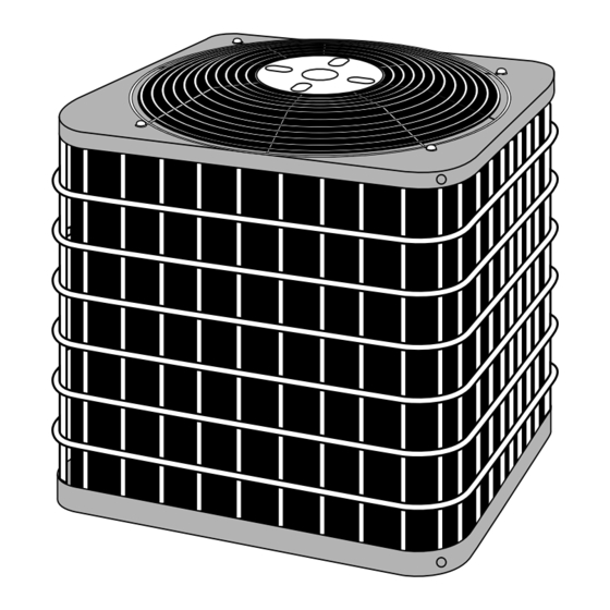
Fig. 1—Model 38BYC
INSTALLATION
Pg 1
10-97
Replaces: 38AYC-1SI/38-6SM
38BYC
A97005
Advertisement
Table of Contents

Related Manuals for Carrier 38BYC


Summary of Contents for Carrier 38BYC
- Page 1 Recognize safety information. This is the safety-alert symbol A97005 When you see this symbol on the unit and in instructions or Fig. 1—Model 38BYC manuals, be alert to the potential for personal injury. Understand the signal words DANGER, WARNING, and CAU- 7.
-
Page 2: Inspect Equipment
NOTE: Avoid contact between tubing and structure OUTDOOR WALL INDOOR WALL CAULK LIQUID TUBE VAPOR TUBE INSULATION THROUGH THE WALL JOIST HANGER STRAP (AROUND VAPOR ″D. (9.53) TIEDOWN ⁄ INSULATION TUBE ONLY) KNOCKOUTS (2) PLACES VAPOR TUBE A94199 Dimensions (In.) MINIMUM 1″... -
Page 3: Fan Coils
10 O'CLOCK 2 O'CLOCK COIL SENSING BULB SENSING BULB EQUALIZER STRAP TUBE SUCTION TUBE 8 O'CLOCK 4 O'CLOCK THERMOSTATIC EXPANSION ⁄ ⁄ IN. OD & SMALLER LARGER THAN IN. OD VALVE A88382 A81032 Fig. 4—Typical TXV Installation Fig. 5—Positioning of Sensing Bulb 4. - Page 4 → Table 1—Refrigerant Connections and Recommended Liquid and Vapor Tube Diameters (In.) LIQUID VAPOR VAPOR (LONG LINE) UNIT SIZE Connection Diameter Tube Diameter Connection Diameter Tube Diameter Tube Diameter 030, 036 1-1/8 048, 060 1-1/8 1-1/8 NOTES: 1. Tube diameters are for lengths up to 50 ft. For tubing lengths greater than 50 ft, consult Residential Split System Long-Line Application Guideline. 2.
- Page 5 on unit rating plate. Contact local power company for correction of ensure wires are not in contact with tubing, sheet metal, etc. → improper voltage. See unit rating plate for recommended circuit Step 11—Compressor Crankcase Heater protection device. When equipped with a crankcase heater, furnish power to heater a NOTE: Operation of unit on improper line voltage constitutes minimum of 24 hr before starting unit.
- Page 6 IMPORTANT: When using outdoor thermostats, W 2 must be CONNECTION energized when requesting supplemental heat. A97536 A97537 Fig. 9—Typical 24-v Circuit Connections using Carrier Model HP Thermostat with Fan Coils and No Outdoor Thermostat, 1 Outdoor Thermostat, or 2 Outdoor Thermostats...
- Page 7 FA, FB, FC, FA, FB, FC, HEAT OTHER FD, FF, FH OTHER FD, FF, FH HEAT OUTDOOR HP THERMOSTAT FAN COIL PUMP HP THERMOSTAT PUMP FAN COIL THERMOSTAT 24 VAC HOT 24 VAC HOT 24 VAC COM 24 VAC COM HEAT STAGE 2 HEAT STAGE 2 COOL/HEAT...
- Page 8 TEMPERATURE SENSOR TEMPERATURE SENSOR SENSOR CONNECTION SENSOR CONNECTION A97538 A97539 Fig. 11—Typical 24-v Circuit Connections using Carrier Model DF Thermostat with Single- or 2-Stage Furnace CARRIER PROGRAMMABLE FK4C HEAT THERMOSTAT FAN COIL PUMP MODEL 2S J1 JUMPER 24 VAC HOT...
- Page 9 RVS COOLING O/W2 NOT USED Y1/W2 24 VAC COM NOT USED TROUBLE OPTIONAL OUTDOOR SENSOR CONNECTION A97543 Fig. 13—Typical 24-v Circuit Connections using Carrier Model HP Thermostat with Smart Heat and No Outdoor Thermostat, 1 Outdoor Thermostat, or Supplemental Heat Relay...
- Page 10 FA, FB, FC, FH OTHER FAN COIL HEAT FA, FB, FC, FH HP THERMOSTAT SMART HEAT PUMP OTHER FAN COIL HEAT HP THERMOSTAT PUMP SMART HEAT 24 VAC HOT 24 VAC HOT 24 VAC COM 24 VAC COM COOL/HEAT STAGE 1 COOL/HEAT STAGE 1 INDOOR FAN...
-
Page 11: Wiring Diagram Notes
WIRING DIAGRAM NOTES: 1. CARRIER THERMOSTAT WIRING DIAGRAMS ARE ONLY ACCURATE FOR MODEL NUMBERS TSTAT _ _ _ _ _ _ _. 2. WIRING MUST CONFORM TO NEC OR LOCAL CODES. 3. SOME UNITS ARE EQUIPPED WITH PRESSURE SWITCH(ES), TEMPERATURE SWITCH, OR 5-MINUTE COMPRESSOR CYCLE PROTECTION. -
Page 12: Care And Maintenance
Allow a tolerance of ± 3°F. areas, such as coastal applications. Copyright 1997 CARRIER Corp. • 7310 W. Morris St. • Indianapolis, IN 46231 38byc1si Manufacturer reserves the right to discontinue, or change at any time, specifications or designs without notice and without incurring obligations.
Need help?
Do you have a question about the 38BYC and is the answer not in the manual?
Questions and answers