Table of Contents
Advertisement
Quick Links
Advertisement
Table of Contents

Subscribe to Our Youtube Channel
Related Manuals for PCB Piezotronics IMI SENSORS 683A101000


Summary of Contents for PCB Piezotronics IMI SENSORS 683A101000
- Page 1 Model 683A101000 Indicator/Controller (for use w/ ICP® sensors) Installation and Operating Manual For assistance with the operation of this product, contact PCB Piezotronics, Inc. Toll-free: 800-959-4464 24-hour SensorLine: 716-684-0001 Fax: 716-684-3823 E-mail: imi@pcb.com Web: www.imi-sensors.com...
- Page 2 Piezotronics, user servicing or repair is critical test. not recommended and, if attempted, may void the factory warranty. Routine PCB Piezotronics maintains an ISO- maintenance, such as the cleaning of 9001 certified metrology laboratory and electrical connectors, housings, and offers calibration services, which are...
- Page 3 50% of the general contact numbers are: replacement cost returned item(s). PCB will provide a price PCB Piezotronics, Inc. quotation replacement 3425 Walden Ave. recommendation for any item whose Depew, NY14043 USA repair costs would exceed 50% of...
- Page 4 PCB工业监视和测量设备 - 中国RoHS2公布表 PCB Industrial Monitoring and Measuring Equipment - China RoHS 2 Disclosure Table 有害物质 汞 镉 六价铬 (Cr(VI)) 多溴联苯 (PBB) 多溴二苯醚 (PBDE) 部件名称 铅 (Pb) (Hg) (Cd) 住房 PCB板 电气连接器 压电晶体 环氧 铁氟龙 电子 厚膜基板 电线 电缆 塑料 焊接...
- Page 5 Component Name Hazardous Substances Lead Mercury Cadmium Chromium VI Polybrominated Polybrominated (Pb) (Hg) (Cd) Compounds Biphenyls Diphenyl (Cr(VI)) (PBB) Ethers (PBDE) Housing PCB Board Electrical Connectors Piezoelectric Crystals Epoxy Teflon Electronics Thick Film Substrate Wires Cables Plastic Solder Copper Alloy/Brass This table is prepared in accordance with the provisions of SJ/T 11364.
- Page 6 ® Model 683A1 ICP Process Indicator/Controller Operating Guide with Enclosed Warranty Information 3425 Walden Avenue, Depew, New York 14043-2495 Phone (716) 684-0003 Fax (716) 684-3823 Toll Free Line 1-800-959-4IMI MANUAL NUMBER: 19163 MANUAL REVISION: C ECN NUMBER: 18874...
-
Page 7: Table Of Contents
Table of Contents Introduction………………………………………………………………………………………. Page 3 General Features, Software Features Specifications……………………………………………………………………………………. Page 4 Controls and Indicators………………………………………………………………………… Page 5 Glossary of Programming Symbols…………………………………………………………… Page 6 Software Logic Tree…………………………………………………………………………….. Page 7 Programming the 683A1..……………………………………………………………………… Page 8 Wiring and Installation………………………………………………………………………… Page 13 Configuring the 683A1 ……………………………………………………………………….. Page 17 Accessories…………………………………………………………………………………….. -
Page 8: Introduction
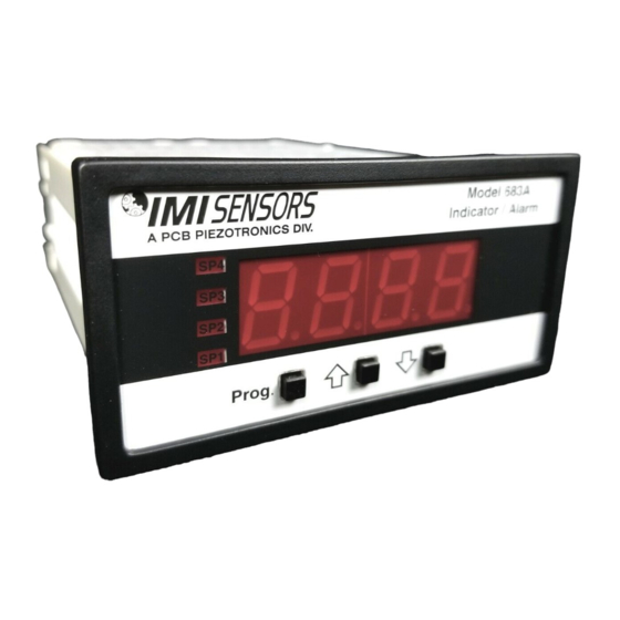
Introduction ® The Model 683A1 ICP Process Indicator/Controller is an intelligent 4-digit modular panel meter with software features for monitoring, measurement, and control applications complete with 0.56” LED in a 1/8 DIN 96x48 case. The 683A1 operates from a single power supply and will supply 24Vdc/4mA excitation for sensor power. The indicator/controller comes equipped with two 5 Amp Form A relays with independent setpoints and time delay. -
Page 9: Specifications
Specifications Input Specs: ..100mV/g ICP ® Sensor Excitation: ..24Vdc/4mA, ±1Vdc/±1mA A/D Converter: ..14 bit single slope Accuracy: ..±2.0% of Scale Factor + 2 counts Frequency Response: 3Hz to 10Khz (Standard) Acceleration: -3dB at 3Hz ±0.5Hz, -3dB at 10kHz ±0.5kHz Velocity: -3dB at 3.5Hz ±0.5Hz, -3dB at 10kHz ±0.5kHz Displacement: -3dB at 3.5Hz ±0.5Hz, 1000Hz max. -
Page 10: Controls And Indicators
Controls and Indicators Front Panel Buttons Program Button button is used to move from one program step to the next. When pressed at the same time as the button, it initiates the calibration mode. When pressed at the same time as the button, it initiates the setpoint setting mode. -
Page 11: Glossary Of Programming Symbols
Glossary of Programming Symbols To explain software-programming procedures, logic diagrams are used to visually assist in following the programming steps. The following symbols are used to represent various functions and associated display elements of the 683A1: Symbol Explanation Symbol Explanation This symbol represents the Text or numbers shown between [ScALE]... -
Page 12: Software Logic Tree
Software Logic Tree The 683A1 is an intelligent meter with a hierarchical software structure designed for easy programming and operation, as shown below in the software logic tree. After the meter has been powered up, the four digits light up for three seconds and then settle to the operational display indicating the input signal. -
Page 13: Programming The 683A1
Programming the 683A1 Digital Scaling The 683A1 meter may be rescaled without applying an external signal by changing the Offset and Scale factor. Offset is the reading that the meter will display for a 0mV input. The Offset may be set to any value from –1999 to +9999. - Page 14 Two Point Analog Output Range Setting and Calibration STEP A Enter the Calibration Mode 1) Press the and the buttons at the same time. Display toggles between [cAL] and [oFF]. 2) Press the button. Display changes from [oFF] to [on]. 1) Press the button.
- Page 15 Decimal Point and Brightness Selection STEP A Enter the Decimal Point and Brightness Mode Through the Sub Menu [CAL]{oFF] 2) Press the and the buttons at the same time. Display toggles between [cAL] and [oFF]. 3) Press the button. Display shows the previous [dp] selection. STEP E Set the Decimal Point 1) Using the buttons, adjust the display to the desired decimal...
- Page 16 Setpoint Setting and Relay Configuration Mode The following programming steps are required to enter the setpoint values and configure the relay functions in a meter with four relays using four setpoints. Generally if less than four relays are installed the software auto detects the missing relays and deletes reference to them from the menu.
- Page 17 STEP J Set Setpoint 3 (SP3) (No [doM] or [dob]) Using the buttons, adjust the display to the desired SP3 value. Press the button. Display toggles between [hYST] and the previous [hYST] setting. STEP K Set the Hysteresis Setting for Setpoint 3 Using the buttons, adjust the display to the desired hysteresis [hYST] value.
-
Page 18: Wiring And Installation
Wiring and Installation Pinout Diagram The Rear View Meter diagram shows the meter with the relay configuration: dual 10 Amp Form C and dual 5 Amp Form A relays. An analog output module is also shown as installed. The 683A1 uses plug-in type screw terminal connectors for all input and output connections. - Page 19 Typical Wiring Diagram (CE Power Supply Option) METALLIC ENCLOSURE 14 15 9 10 11 ICP SENSOR/ SIMULATOR N/C N/C N/C N/C SHIELD CORCOM RV OUTPUT 3EB1LB EMI FILTER NEUTRAL LINE To Maintain Conformance I/O Shields must be connected to Pin 3 on the Panel Meter and all Supplied Accessories must be wired as shown (Power Supply Option 2).
- Page 20 Pin Descriptions Input Signal - Pins 1 to 6 ® Pin 1 +ICP Sensor Excitation/Signal ® Pin 2 -ICP Sensor Excitation ® Pin 3 Sensor Shield (if applicable) Pin 4 + RV Output (Analog Sensor Signal) Pin 5 - RV Output (Analog Sensor Signal) Pin 6 No Connection Relay Output - Pins 8 to 12...
- Page 21 Case Dimensions and Panel Cutout PAGE 16...
-
Page 22: Configuring The 683A1
Configuring the 683A1 ® Interface PC Board Diagram ® The ICP Interface Board Diagram shows the location of the internal Selector DIP switch. This DIP switch is Switch used to configure the indicator for various sensor and vibration ranges. The PC Board is accessible through the back of the indicator by removing the Screw Terminal Plugs and back panel. -
Page 23: Accessories
Accessories NEMA 4X Lens Cover The lens cover is designed to be dust and water proof to NEMA-4X standards. The lens cover consists of a base and cover with a cam hinge and key-lock locking device. An O-ring, or neoprene gasket forms a seal between the base and the panel. - Page 24 Metal Surround Case The meter’s plastic case is made from a fire retardant polycarbonate. A metal surround case can be ordered to enhance the meter’s fire retardant capabilities and also provide shielding against electromagnetic interference (EMI). The metal case slides over the polycarbonate case and is held firmly in place by spring-type non-return clips.
-
Page 25: Esd Sensitivity
Warning 2 – ESD sensitivity This equipment is designed with user safety in mind; however, the protection provided by the equipment may be impaired if the equipment is used in a manner not specified by PCB Piezotronics, Inc. Caution 1 – ESD sensitivity Cables can kill your equipment. -
Page 26: Ordering Information
Ordering Information IMI Part Number: 683A 1 1 0 2 0 3 Basic Model Number 683A Sensor Input ® 100mV/g ICP Sensor Power Supply 85-265Vac/95-370Vdc 18-48Vac/10-72Vdc 85-265Vac/95-370Vdc CE Certified. Analog Output* None Isolated 16 bit user scalable 4-20mA retransmit. Additional Relay Output* None Dual 10 Amp Form C Relays (SPDT) Dual 5 Amp Form A Relays (SPST) -
Page 27: Warranty, Service & Return Procedure
Warranty IMI instrumentation is warranted against defective material and workmanship for 1 year unless otherwise expressly specified. Damage to instruments caused by incorrect power or misapplication, is not covered by warranty. If there are any questions regarding power, intended application, or general usage, please consult with your local sales contact or distributor. -
Page 28: Customer Service
Customer Service IMI, a division of PCB Piezotronics, guarantees Total Customer Satisfaction. If, at any time, for any reason, you are not completely satisfied with any IMI product, IMI will repair, replace, or exchange it at no charge. You may also choose, within the warranty period, to have your purchase price refunded. - Page 29 All specifications are at room temperature unless otherwise specified. In the interest of constant product improvement, we reserve the right to change specifications without notice. 3425 Walden Avenue, Depew, NY 14043 ® is a registered trademark of PCB Piezotronics, Inc.
Need help?
Do you have a question about the IMI SENSORS 683A101000 and is the answer not in the manual?
Questions and answers