Advertisement
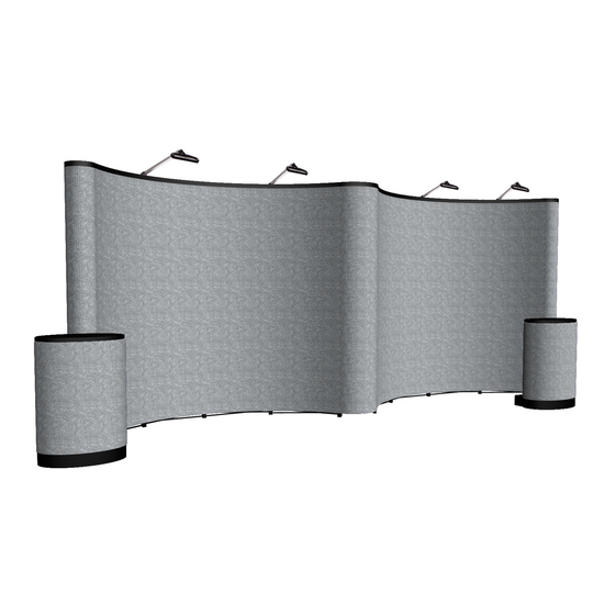
Premium 20' Gullwing Floor Display (Fabric Only)
Congratulations on the purchase of your
Premium Pop-Up Display.
Owner's Manual
Includes:
Parts List
Assembly Instructions
Please read all of the information carefully and
contact your distributor or supplier with any questions.
Parts List
Important: Before you begin please count
and inspect all pieces.
2 � 12�quad curved frame (A)
36 � Magnet Bars (B)
2 � Hardware Bag (C)
2 � Double LED Light Kit (D)
2 � Universal LED Light Clip Kit (E)
8 � Fabric Center Panels (F)
3 � Fabric End Panels (G)
2 � Fabric Case�to�Counter Kit (H)
2 � Oval Shipping Case w/wheels (I)
Assembly Instructions
Step 1
Remove frames (A) from cases. Standing in front or behind expand the frames (A) by pulling up from the
middle of the frame.
(B)
(A)
(C)
(D)
Step 2
Select the Universal LED Light Clip, item # 150045, (E) and insert into the base of
LED Light (D).
Step 3
Plug power cord from the light kit into base of light (D). Then slide light (D) with
clip attachment inserted, onto light clip on the top of the frame (A). If you cannot
locate the light clips on the frame, check to make sure the frame is not upside down.
Repeat for second light and finished expanding frames.
(G)
(E)
(F)
(found inside LED Light Kit)
Item # 332226
Wrap
(H)
Counter Top
(I)
Advertisement
Table of Contents

Summary of Contents for Arise Premium 332226
- Page 1 Premium 20’ Gullwing Floor Display (Fabric Only) Item # 332226 Congratulations on the purchase of your Premium Pop-Up Display. Owner’s Manual Includes: Parts List Assembly Instructions Disassembly Instructions Storage Instructions Care Instructions Warranty Information Please read all of the information carefully and contact your distributor or supplier with any questions.
- Page 2 Assembly Instructions (cont.) Step 4 Secure the stability of the unit by engaging the MAGNAFORCE™ locking bars into place. Step 5 Beginning at the bottom and working up, attach the magnet bars (B) by aligning the cut�outs on the bars with the center of the hub on the frame (A).
- Page 3 Disassembly Instructions (cont.) Step 2 Carefully place rolled panels in shipping cases (H), fabric/graphic side out. Roll panels so they are along the perimeter of case. Step 3 Remove all magnet bars (B) from frame (A), and place in hardware bags (C). Step 4 Disengage the locking bars (see Assembly Step 4).
Need help?
Do you have a question about the Premium 332226 and is the answer not in the manual?
Questions and answers