
Summary of Contents for Procon ESENET
- Page 1 ESENET Ethernet gateway for CANopen genset controls User manual Edition 2 UMESENET-2201...
- Page 2 We provide an electronic support and feedback system for our proconX products. It can be accessed through the following web link: https://www.proconx.com/support Your feedback and comments are always welcome. It helps improving this product. Contact For further information about the ESENET product please visit https://www.proconx.com/esenet...
-
Page 3: Table Of Contents
Configuring and commissioning ................ 24 Configuring Ethernet and IP ............... 24 Configuring CAN and CANopen ..............25 Remote restarting the device ..............25 6 Running Toolkit via the ESENET gateway ............... 27 How it works ..................... 27 Installation ......................28 Running Toolkit ....................30 TCP Ports ...................... - Page 4 5.9 Restart confirmation page ................... 26 6.1 Toolkit network selection ..................30 6.2 Entering the ESENET gateway’s IP address in Toolkit ........... 31 6.3 Successful CAN over TCP/IP connection ............... 31 6.4 Example of Toolkit indicating a communication error ......... 32 7.1 "Configure interfaces"...
- Page 5 Tables 2.1 LED diagnostic codes .................... 6 3.1 Power supply connector pinout ................11 3.2 CAN connector pinout ..................11 3.3 Ethernet connector pinout .................. 12 3.4 Diagnostic port connector pinout ............... 13 7.1 Modbus Slave ID, CANopen Node-ID & COB-ID relationships ......33 7.2 Supported Data Protocols ...................
- Page 6 This page intentionally left blank UMESENET-2201...
-
Page 7: Important User Information
• Apply appropriate personal protective equipment and follow safe electrical practices. • Turn off all power supplying the equipment in which the ESENET is to be installed before installing, wiring or removing the ESENET. • Always use a properly rated voltage sensing device to confirm that power is off. -
Page 8: Document Conventions
Document conventions Throughout this manual we use the following symbols and typefaces to make you aware of safety or other important considerations: Indicates a potentially hazardous situation that, if not avoided, could result in death or serious injury. Indicates a potentially hazardous situation that, if not avoided, could result in damage to equipment. -
Page 9: Introduction
CAN to offer short Modbus/TCP poll cycles as well as concurrent access. A single ESENET added to the CAN network will make all Visualisation Data of connected Woodward CANopen controls available without adding additional load to the CAN bus communication. -
Page 10: Features
• Remote control & monitoring • Data logging Features The ESENET gateway provides the following key features: • Multiple concurrent Modbus/TCP connections • Toolkit interface to configure Woodward controls via Ethernet • Supports Easygen 3500, 3400, 3200, 3100, 2000 and 1000 models •... -
Page 11: Quick Start Checklist
Introduction Quick start checklist • Read this set of instructions properly and in its entirety. • Mount the unit. • Connect the power. Do not connect yet CAN bus or serial ports. • Configure the Ethernet communications settings with a web browser (using an Ethernet crossover cable) or with a terminal program like HyperTerminal (using a null modem cable) •... - Page 12 This page intentionally left blank UMESENET-2201...
-
Page 13: Description
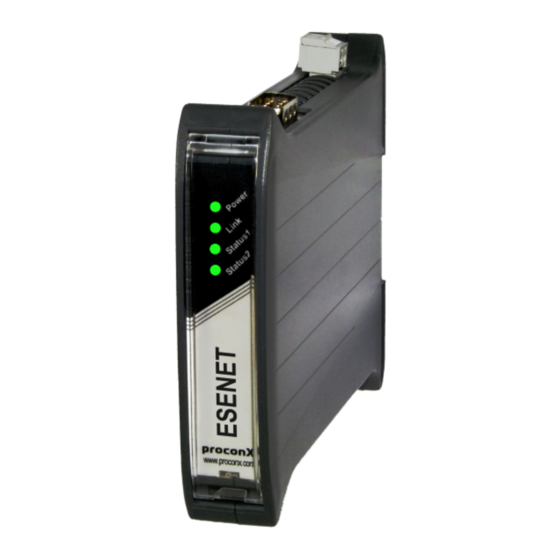
CAN connector LED indicators Four LEDs located at the front panel indicate the status of the ESENET. The LEDs assist maintenance personnel in quickly identifying wiring or communication errors. A LED test is exercised at power-up, cycling each LED off, green and then red for approximately 0.25 seconds. - Page 14 The following table outlines the indicator condition and the corresponding status after the power-on self-test has been completed: Function Condition Indication Power Power No power applied to the device. Green Power supply OK Link Ethernet link No Ethernet link Green Ethernet link OK Status1 Device status...
-
Page 15: Principles Of Operation
Woodward controls, the ESENET starts to buffer all multiplexed visualisation data of such device into its internal data tables. The ESENET also acts as a Modbus server on the Ethernet interface. It accepts connections and Modbus queries from Modbus master devices. The Modbus registers are then served from the ESENET's internal data tables. - Page 16 This page intentionally left blank UMESENET-2201...
-
Page 17: Installation
Regulatory notes 1. The ESENET is suitable for use in non-hazardous locations only. 2. The ESENET is not authorized for use in life support devices or systems. 3. Wiring and installation must be in accordance with applicable electrical codes in accordance with the authority having jurisdiction. -
Page 18: Din Rail Mounting And Removal
DIN rail mounting and removal The ESENET gateway is designed to be mounted on a 35 mm DIN rail according to DIN/ EN 50022. The enclosure features a 35 mm profile at the back which snaps into the DIN rail. -
Page 19: Powering The Esenet
Wiring the CAN interface The CAN interface connects the ESENET to the Woodward CANopen based controls. The CAN connector is a male 9-pin D-sub type located at the top side of the mounted unit (refer to Figure 2.1, “Location of connectors”... -
Page 20: Connecting Ethernet
• The network must be terminated at both ends with its characteristic impedance, typically a 120 Ohm 1/4 W resistor. • Maximum number of electrically connected CAN nodes is 64 • Maximum CAN cable length is 250 m (820 ft) and is derated depending on bit rates and cable type. -
Page 21: Diagnostic Port Connector Pinout
• The shield must not be connected to the GND pin. To connect the ESENET to a PC (Personal Computer) or any other device with data terminal equipment (DTE) pinout you need a null-modem or cross-over cable. - Page 22 This page intentionally left blank UMESENET-2201...
-
Page 23: Ethernet & Ip Configuration
“Temporarily changing the IP settings on your PC”). In order to connect to the ESENET via TCP/IP, your PC must be on same IP subnet as the gateway. In most situations this means that the first three numbers of the IP address have to be identical. -
Page 24: Ip Setup Using A Terminal Program Like Hyperterminal
IP setup using a terminal program like HyperTerminal 1. Connect a null modem RS-232 cable between your PC and the ESENET's diagnostic port. 2. In Windows XP, click Start, point to All Programs, point to Accessories, point to Communications, and then click HyperTerminal. -
Page 25: Temporarily Changing The Ip Settings On Your Pc
This method involves manually assigning an IP address to your PC in the same subnet as the gateway. The default subnet of the gateway is 169.254.0.0/16. 1. Connect the ESENET to your Ethernet network. 2. On a Windows PC, open the Control Panel and double-click on Network Connections. - Page 26 8. Click Configuration… and then Ethernet & IP in the menu on the left side of the page. 9. Enter the IP address, subnet mask, and gateway address assigned to your ESENET, then click Save. 10.Restore your computer’s original settings.
-
Page 27: Web Browser Based Management
Once you made sure that your PC is configured to be on the same subnet as the ESENET, start your web browser. In the address box, type the IP address of your device (169.254.0.10 is the default), and then press Enter. (See Chapter 4, Ethernet & IP... -
Page 28: Monitoring And Diagnostic
In order to connect to the ESENET via TCP/IP, your PC must be on same IP subnet as the gateway. In most situations this means that the first three numbers of the IP address have to be identical. Monitoring and diagnostic The ESENET offers several web pages which allow monitoring of the status of the different communication networks and the device performance. -
Page 29: Modbus Connection Status
CAN’s built in fault confinement mechanism has set the node to bus-off state due to excessive errors on the CAN bus. This alarm indicates a wiring error. The ESENET will not transmit or receive any message on the CAN bus once entered this state. The device needs to be manually restarted on order to recover from this fault. -
Page 30: Can Communication Status
Rx time-outs A counter that increments if the master connection has timed out. Subsequently the connection is terminated by the ESENET. A time-out occurs if no Modbus request is received from a connected client within a 10 second period. Tx time-outs Number time-outs occurred when attempting to send a reply message. -
Page 31: Finding The Firmware Version And Serial Number
WAIT The presence of a supported Woodward CANopen based control has been detected however the ESENET is currently waiting to receive a complete visualisation data set. TIME-OUT No CANopen PDO was received for a period of 1 second. A Woodward control must be configured to transmit cyclically visualisation data using a TPDO with a specific COB-ID number and the correct Data Protocol. -
Page 32: Configuring And Commissioning
The firmware version that is installed on the ESENET. Serial number The serial number of the ESENET. The serial number is specific to your device. Configuring and commissioning The configuration pages are accessed by clicking on the Configuration… menu entry on the menu bar which then expands a configuration sub-menu. -
Page 33: Configuring Can And Canopen
Configuring CAN and CANopen The ESENET gateway itself does not require any CANopen configuration. No Node-ID is allocated for the ESENET because it operates as a CANopen consumer and client only. However the CANopen settings of the connected Woodward controls must be configured accordingly. -
Page 34: Restart Confirmation Page
Click on the Restart button to perform a restart of the device. The restart is confirmed with the following notification: Figure 5.9: Restart confirmation page Please allow a few seconds before continuing working with the device as it has to fully start-up first, before being able to respond to further web browser requests. After a remote restart a Watchdog reset alarm is shown on the device' home page. -
Page 35: Running Toolkit Via The Esenet Gateway
• PC with installed Woodward Toolkit How it works For Toolkit to recognise the ESENET gateway as a CAN interface, a virtual CAN port needs to be installed on the Toolkit PC. proconX provides a CAN Library for Toolkit installer which replaces Tookit’s standard Kvaser USB CAN driver with a custom CAN library. -
Page 36: Installation
Installation 1. To install, run the self-extracting Installer executable and click Next to continue: 2. Click Next to confirm the installation: UMESENET-2201... - Page 37 Running Toolkit via the ESENET gateway 3. The installation is completed, click Finish to exit the installer: You can revert back to Toolkit’s original Kvaser CAN library by simply uninstalling the proconX CAN Library for Toolkit. UMESENET-2201...
-
Page 38: Running Toolkit
Running Toolkit Launch Toolkit in the usual manner and click on the Connect button to open the Select a network drop-down box. In the Network selection list, choose USB Kvaser Simulated 1 as CAN interface and confirm with Connect. Figure 6.1: Toolkit network selection The USB Kvaser Simulated 1 selection will not show if the proconX CAN Library for Toolkit is not installed! UMESENET-2201... -
Page 39: Entering The Esenet Gateway's Ip Address In Toolkit
Running Toolkit via the ESENET gateway A dialog box will open and ask for the IP address of the connected ESENET gateway. Enter the correct IP address for the ESENET gateway and click OK. Figure 6.2: Entering the ESENET gateway’s IP address in Toolkit On successful connection, the status in Toolkit’s status line will change from... -
Page 40: Tcp Ports
In case of a connection error or a communication error, the Toolkit status will revert back to either Establishing Connection or Reconnecting. In this case terminate the session and establish a new session by clicking Disconnect and Connect again. Figure 6.4: Example of Toolkit indicating a communication error TCP Ports The TCP/CANopen-SDO bridge uses the same TCP port as Modbus/TCP which is port 502. -
Page 41: Configuration Of Connected Woodward Controls
Chapter 7. Configuration of connected Woodward controls The ESENET has been designed to keep the configuration effort required to connect the gateway with Woodward CANopen devices to a minimum. In most situations no additional configuration is necessary to get the ESENET communicating with an Easygen-3000 series control. -
Page 42: Specific Information For Easygen-3000 Series Controls
Modbus Slave ID CANopen Node-ID Easygen-3000/LS-5 TPDO COB-ID dec DTSC-200 TPDO COB-ID dec (hex) (hex) 397 (0x18D) 1165 (0x48D) 398 (0x18E) 1166 (0x48E) 399 (0x18F) 1167 (0x48F) 400 (0x190) 1168 (0x490) Table 7.1: Modbus Slave ID, CANopen Node-ID & COB-ID relationships Data Protocol of the Transmit PDOs The Data Protocol of the Transmit PDOs must be set according to the Woodward CANopen device used. -
Page 43: Can Interface
ID under which the Easygen data can be retrieved. Transmit PDOs In order for the ESENET gateway to receive cyclic data updates from the Easygen, one of the five available Transmit PDOs (TPDO) must be configured. Typically Tranmsit PDO 1 is already pre-configured for that purpose, but any of the five TPDOs could be used for that purpose. -
Page 44: Specific Information For Ls-5 Controls
In the following example for an Easygen with device ID of 1 and Node-ID of 1, the Transmit PDO 1 is used to send data updates every 20 ms: Figure 7.3: "Transmit PDOs" menu in Woodward Toolkit All COB-IDs used in the CAN network must be unique. Please make sure that a COB-ID is only configured once. -
Page 45: Can Interface
LS-5 data can be retrieved. One could for example use Node-IDs 1 to 8 for Easygens and Node-IDs 8 to 16 for LS-5s. Transmit PDOs In order for the ESENET gateway to receive cyclic data updates from the LS-5, one of the five available Transmit PDOs (TPDO) must be configured. Typically Tranmsit PDO 1 UMESENET-2201... -
Page 46: Specific Information For Dtsc-200 Controls
is already pre-configured for that purpose, but any of the five TPDOs could be used for that purpose. If for example Transmit PDO 1 is used, then: • parameter 9600 COB-ID must be set to 384 + Node-ID, • parameter 8962 Selected Data Protocol to 5301 and •... -
Page 47: Can Interfaces
Configuration of connected Woodward controls Figure 7.7: P arametrize dialog in LeoPC software CAN interfaces • Parameter Device number determines the Modbus Slave ID under which the DTSC-200 data can be retrieved. It must be set to a unique number in the network. •... -
Page 48: Transmit Pdos
Transmit PDOs In order for the ESENET gateway to receive cyclic data updates from the Easygen, one of the four available Transmit PDOs (TPDO) must be configured. Typically Tranmsit PDO 4 is already pre-configured for that purpose, but any of the four TPDOs could be used for that purpose. -
Page 49: Tpdo Section In "Parametrize" Dialog Of Woodward's Leopc Software
Configuration of connected Woodward controls Figure 7.9: TPDO section in "Parametrize" dialog of Woodward’s LeoPC software All COB-IDs used in the CAN network must be unique. Please make sure that a COB-ID is only configured once. If TPDO or RPDO COB-ID entries are referring to an already used COB-ID, either disable that PDO or change the COB-ID. - Page 50 This page intentionally left blank UMESENET-2201...
-
Page 51: Modbus Data Reference
This chapter describes how process data and configuration data of the Woodward controls are organized in logical blocks and accessed via Modbus. The ESENET supports two principal Modbus data tables one for visualisation and one for configuration & remote control. These data tables are organised in a similar manner to the serial Modbus adress ranges of the Woodward controls. -
Page 52: Visualisation Data Table
Registers in this data table can only be accessed if the CAN communication between ESENET and the Woodward control has been established. If this is not the case, Modbus exception code 0B Gateway target device failed to respond is returned, indicating the Woodward control is not present on the CAN bus. -
Page 53: Easygen-3000
Modbus data reference Please consult the appropriate Woodward manual for exact layout, encoding and representation of the data in the Visualisation Data Table. Some examples for the most commonly used Woodward controls are shown in the following tables: Easygen-3000 Address Register Easygen-3000 interface manual designator block... -
Page 54: Easygen-1000
Easygen-1000 The following table describes the layout of the Modbus data tables when interfacing to the Easygen-1000 using Data Protocol Parameter No. 3190/Object 2C76h. Address Register Word size Parameter # Easygen-1000 interface manual designator block address 50001 16 bit Protocol-ID, 4003 50002 32 bit Generator: Voltage V L12... -
Page 55: Modbus Function Codes
For details about physical units and encoding of the value, please refer to chapter "CANopen: Mapping-Parameter" in the "easYgen-1000 Series - Interface" manual. Modbus function codes The ESENET supports the Modbus function codes 03, 04, 06 and 16. A maximum of 125 16-bit words can be requested with Modbus command 04. Modbus... -
Page 56: Modbus Exception Codes
Modbus exception codes The following table lists the Modbus exception responses sent by the ESENET gateway instead of a normal response message in case of an error: Modbus exception Exception name Reason code Illegal function A Modbus master sent a Modbus function which is not supported by the gateway. -
Page 57: Decommissioning
Decommissioning Chapter 9. Decommissioning Before disconnecting the ESENET unit please follow the rules in the section called “Safety Precautions”. Disconnecting 1. Ensure that the system power and external supplies have been turned off. 2. Disconnect power supply plug. 3. Disconnect all I/O cables. - Page 58 This page intentionally left blank UMESENET-2201...
-
Page 59: A Specifications
Specifications Appendix A. S pecifications Product name ESENET Interfaces Ethernet Serial ports 1 for diagnostics (RS-232) User interface LED indicators Power (green), Ethernet link (green), 2 status (bi-color red/green) Monitoring & configuration Web browser based Diagnostic High availability features Watchdog supervision, brown-out detection... -
Page 60: Dimensions
Electrostatic discharge EN 61000-4-2 Radiated RF EN 61000-4-3 Fast transients EN 61000-4-4 Conducted RF EN 61000-4-6 Enclosure Material Self-extinguishing PC/ABS blend (UL 94-V0) Mounting 35 mm DIN rail (EN 60715) Classification / Type rating IP 20 / NEMA Type 1 Cooling Convection Environmental... -
Page 61: Glossary
Glossary Glossary Electromagnetic compatibility Electromagnetic interference Electrostatic discharge. ESD can damage 10BASE-T electronic equipment. 10 Mbit/s twisted pair Ethernet standard. Standardized in IEEE 802.3i IEEE Institute Electrical Electronics APIPA Engineers Automatic Private IP Addressing Ingress Protection Rating standardized in Controller area network. Standardized in ISO IEC 60529. - Page 62 Predefined Connection Set The CANopen Predefined Connection Set defines standard COB-IDs for PDOs and SDOs. RPDO CANopen Receive Process Data Object. Process data the device is consuming. RS-232 See EIA-232. CANopen Service Data Object. TPDO CANopen Transmit Process Data Object. Process data the device is producing.
-
Page 63: Index
Index Index EMC, 9 enclosure DIN rail clip, 5 front cover, 5 mounting, 10 About, 23 red hook, 10 Accumulative connections, 22 removal, 10 ACTIVE, 21 Ethernet, 12, 24 APIPA, 15 settings, 24 exception codes, 48 Brown out reset, 20 BUS-OFF, 21 faults, 20 features, 2... - Page 64 register, 45, 45, 45, 47 operating, 11 Slave ID, 43 terminal program, 16 status, 22 termination mounting, 10 CAN, 12 rules, 10 TIME-OUT, 23 twisted pairs, 12 Tx time-outs, 22 nodes maximum Unpacking, 9 CAN, 12 ventilation, 11 PASSIVE, 21 vibration, 10 pinout CAN, 11...
- Page 65 Notes Notes UMESENET-2201...
- Page 66 This page intentionally left blank UMESENET-2201...
Need help?
Do you have a question about the ESENET and is the answer not in the manual?
Questions and answers