Table of Contents
Advertisement
Advertisement
Table of Contents

Summary of Contents for MPH Sure Shot
- Page 1 Sure Shot™ Laser Speed Measurement User’s Manual 1 ...
- Page 2 Copyright 2018, MPH Industries, Inc. – All Rights Reserved Printed in U.S.A. No part of this work, covered by the copyrights hereon, may be reproduced or copied in any form or by any means – graphic, electronic, mechanical, including photocopying, taping, or information storage and retrieval systems – without the written permission of MPH Industries, Inc. Customer Service (888) 689‐9222 2 ...
-
Page 3: Table Of Contents
ABLE OF ONTENTS 2 Table of Figures ............................. 5 3 Understanding Laser Safety ........................ 6 3.1 Eye Safety ............................ 6 4 Introduction ............................ 8 4.1 Getting Started .......................... 8 4.2 Packing List ............................ 8 5 Features and Layout .......................... 9 5.1 Features ............................ 9 5.2 Front View ............................. 9 5.3 Side Views ........................... 10 5.4 Rear View ............................ 10 5.5 Installing the Batteries ........................ 11 5.6 ... - Page 4 7.4 USB Ports ............................. 35 7.4.1 Host Port (Type‐A) ....................... 35 7.4.2 Device Port (Type‐B) ...................... 35 7.5 Supplying Power ......................... 35 7.5.1 Battery Power ........................ 35 7.5.2 Corded Power ........................ 35 7.5.3 Auto‐Sleep Mode ........................ 36 7.5.4 Auto Power Off ........................ 36 8 Troubleshooting the Laser ........................ 37 9 Care and Maintenance ........................ 38 9.1 Cleaning the Sure Shot™ Optics .................... 38 10 Accessories and Options ......................... 39 10.1 12 Volt Car Power Adapter ...................... 39 10.2 USB Device Cable ........................ 39 10.3 Shoulder Stock .......................... 39 11 Specifications .......................... 40 ...
-
Page 5: Table Of Figures
ABLE OF IGURES Figure 1‐ Sure Shot™ Laser.......................... 8 Figure 2‐ Front View ............................ 9 Figure 3‐ Left and Right Side Views ...................... 10 Figure 4‐ Rear View ............................. 10 Figure 5‐ System Initialization Screens ....................... 12 Figure 6‐ Normal Operational Mode Shot Example .................. 14 Figure 7‐ Range Only Shot Example ...................... 14 Figure 8‐ Home Screen .......................... 16 Figure 9‐ Range Mode Select Popup Window .................... 17 Figure 10‐ Unit Test Menu Screens ...................... 18 Figure 11‐ Main Menu Screen ........................ 19 Figure 12‐ Speed Menu Screens ......................... 20 Figure 13‐ Following Too Close Menu Screens ................... 22 Figure 14‐ Stopwatch Menu ........................ 23 Figure 15‐ Set Distance .......................... 24 Figure 16‐ Measure Distance ........................ 25 Figure 17‐ Firing Stopwatch ........................ 25 Figure 18‐ HUD Menu Screens ........................ 26 Figure 19‐ Audio Menu Screen ........................ 27 Figure 20‐ System Menu Screens ........................ 28 Figure 21‐ System Info Screen ........................ 29 ... -
Page 6: Understanding Laser Safety
always be taken when using your Sure Shot™ laser. Sure Shot™ is a Class 1 Laser product which does not exceed a PRF of 200Hz, a pulse width of 30 nsec nor a laser power of 175 µW. It has a Class I Laser Product label affixed to the unit. CAUTION: MODEL: DO NOT VIEW WITH S/N: OPTICAL INSTRUMENTS Caution: The use of controls or adjustments or performance of procedures other than those specified herein may result in hazardous radiation exposure. Any certifications included are void if the product is opened, altered, installed in other equipment or used for purposes other than intended by the manufacturer. Using any charger other than those supplied by MPH Industries will also void the certification. Certain municipalities and countries require settings to differing measurements (mph or km/h). Your unit is factory set to the appropriate unit of measurement. The pictures/drawings/illustrations in this manual are for illustration only and are shown in miles per hour and feet as well as kilometers per hour and meters. 3.1 E YE AFETY The Sure Shot has been certified as a Class I device as defined by the Center for Devices and Radiological Health (CDRH) arm of the Food and Drug Administration which is tasked with ensuring the safety of all laser devices sold in the United States. Class I is the safest classification of laser products in terms of eye safety. While the Sure Shot is relatively low risk, the use of optical instruments with this product will increase eye hazard. Do NOT point this laser at anyone with optical viewing devices within 50 feet of the operator. Although optical viewing instruments may increase eye hazard, it is unlikely that actual damage can occur. Prescription eyeglasses, contact lenses, and sunglasses are not considered optical gain devices ... - Page 7 Optical devices that provide magnification may increase the risk of eye‐hazard. These include binoculars, telescopes and magnifying glasses. 7 ...
-
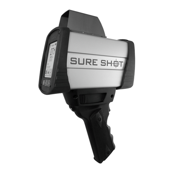
Page 8: Introduction
NTRODUCTION MPH Industries, Inc. designed the Sure Shot™ laser with the police officer in mind. The laser is easy to operate and includes the performance and features needed for today's busy traffic enforcement environment. The Sure Shot™ is one of the most ergonomic and flexible laser devices available, providing full functionality and many options. 4.1 G ETTING TARTED Setting up and using your new Sure Shot Laser unit. Figure 1‐ Sure Shot™ Laser 4.2 P ACKING Please check to make sure the following items that were ordered are included in your shipment, such as: Sure Shot™ Laser Device Soft Carrying Case (if applicable) AA Batteries 12 VDC USB Power cable (if applicable) Operator’s Manual Additionally, you may have received some of the following optional parts: ‐ Monocular ‐ Shoulder Stock 8 ... -
Page 9: Features And Layout
EATURES AND AYOUT This section will identify the physical features of your Sure Shot laser. 5.1 F EATURES 2.7 inch Transreflective LCD display Speed‐adjusted frequency tones Resistive touchscreen – works even with Rubber 1911 grip base gloves Protective ruggedized bumpers Bright OLED heads‐up display ¼‐20 Shoulder stock mount Glass lenses Connections Three ranging modes of operation ‐ o USB Normal, Obstructed and Weather o Bluetooth v2.1+EDR (option) Shot log – stores up to the last 500 shots Power button with date and time ... -
Page 10: Side Views
5.3 S IDE IEWS Figure 3‐ Left and Right Side Views 5.4 R EAR Figure 4‐ Rear View 10 ... -
Page 11: Installing The Batteries
NSTALLING THE ATTERIES Open the battery compartment at the base of the laser handle by pulling the latch release toward the door hinge. Install four charged AA batteries into the battery compartment at the base of the handle and close the compartment by pressing the door closed and pushing the door release latch back into a locked position. Be sure to insert the batteries in the handle in the proper orientation as shown inside the battery compartment. NOTE: If rechargeable NiMH batteries are to be used, make sure you do not mix the rechargeable batteries with alkaline batteries. 5.6 T URNING THE ASER N AND 5.6.1 Turning the Laser On To turn the laser on simply press the Power button below the touchscreen display. The laser will initiate its startup sequence of self‐tests, verify the device is in proper working order and then present the operator with the default Home screen display. The unit is now ready to fire based on the last configuration settings stored in the laser. If the self‐tests did not all pass, the laser will display the error and cease to operate until the issue is resolved. If the batteries are too depleted, the laser may display a LOW VOLTAGE message, a depleted battery symbol in the HUD or not power on at all if too low. 5.6.2 Turning the Laser Off To turn the laser off simply press and hold the Power button below the touchscreen for three seconds. All configurable current settings will be retained for the next time the laser is powered on. 11 ... -
Page 12: System Operation
YSTEM PERATION 6.1 S TARTING THE ASER Simply press the Power button on the display panel to start the laser. As the system prepares for operation the screen will display the MPH logo and go through several internal checks. Figure 5‐ System Initialization Screens The display’s pixels can be checked as a checkerboard pattern displays and then reverses allowing you to identify any pixels that are stuck on or not illuminating. The laser will then proceed to check the Non‐volatile memory (EEPROM), the internal laser timing circuit and the internal crystal. If any of these tests fail, the testing will immediately stop and the test result will show FAIL on the screen. If the tests do not fail, the screen will display PASS for each test. The next page will check to make sure the flash memory, main microcontroller and display microcontroller checksums are all correct. The final internal check will list the serial number of the unit itself. As all of these internal tests are happening on the display, the heads up display (HUD) will also be going through a segment check as well. Once the unit has powered up barring any failures, the display will go directly to the HOME screen and the unit will be ready to use. 6.2 F IRING THE ASER Simply hold, aim and fire. 1. Hold the laser close and aim the reticle (crosshairs or other reticle) onto a specific target. 2. Once the target is identified in the HUD, simply hold the reticle on the target without moving the laser and pull the trigger until the target has been acquired at which time the laser will sound an auditory tone to signify the speed and/or range was calculated. 12 ... -
Page 13: Powering Down The Laser
ASER When you are finished using the laser, simply press and hold the power button on the display for about three seconds. The unit will begin its internal shutdown sequence and turn off. 6.4 W ’ ? S GOING ON BEHIND THE SCENES When the laser is fired, many laser light pulses get emitted out of the device. As they hit a target and reflect back toward the laser and are received, an internal timing mechanism keeps track of how long they took to make the journey. Knowing that the speed of light is a constant value, we can derive the total distance traveled based on the time. Because this distance includes the path from laser to target to laser, we simply divide the total distance by two to determine the target distance from the laser. As additional pulses are transmitted and received, an internal calculation will determine both the speed and direction the target is moving. 6.5 R ’ ?) ETRIEVING HOT ATA S IN A SHOT Not every shot of the laser will return the same data. Depending on how the laser is configured, different data will be returned. In the normal operational mode (Figure 6), each successful laser shot should return the following information: ‐ Time and date of the shot, ‐ Speed calculated for the target (if a speed is detected), ‐ Units of measure for the speed (mph, km/h, etc.), ‐ Direction the target was moving, ‐ Distance from the laser at which the target was captured, ‐ Corresponding distance units of measure. 13 ... - Page 14 Figure 6‐ Normal Operational Mode Shot Example In the Range Only operational mode (Figure 7), each successful laser shot should return the following information: ‐ Time and date of the shot, ‐ Distance from the laser at which the target was captured, ‐ Corresponding distance units of measure. Figure 7‐ Range Only Shot Example Once the shot data has been captured, the laser unit will display the captured information on the displayed HOME screen as well as display some of that information in the HUD depending on how HUD settings are configured. 14 ...
-
Page 15: Approaching And Receding Targets
The HOME screen information will continue to be displayed until one of the following scenarios occurs: Another shot is fired (if Display Lock is not enabled), The menu system of the laser is accessed, The laser enters into sleep mode, The unit is powered off. The power to the laser is interrupted or depleted. 6.6 A PPROACHING AND ECEDING ARGETS The Sure Shot™ laser can measure the speed of both approaching (oncoming) and receding targets. Approaching targets will display a direction arrow pointing down (toward the user) while receding targets will display a direction arrow pointed up (away from the user). The directionality sensitivity can be set to both directions (default on power on) or to approaching or receding only by using the Directional icon in the Main Menu. Target speeds in the HUD will show a positive number for approaching targets and a negative number for receding targets. 15 ... -
Page 16: Laser Controls And Functions
ASER ONTROLS AND UNCTIONS 7.1 T OUCHSCREEN ISPLAY The touchscreen display interface allows you to access various functions of the laser. The touchscreen can be used with or without gloves and is transreflective which means it actually displays better in brighter conditions. 7.1.1 Home Screen The HOME screen (Figure 8) is the primary display used during operation of the laser. This screen displays all of the common operating information along with displaying the results of the last laser shot. Figure 8‐ Home Screen 7.1.1.1 Target Speed The most recent captured speed is prominently displayed for easy readability. The units of speed measurement are visible next to the target speed. If the laser is configured in Range Only operational mode, this area will display the words RANGE ONLY and the target speed units will be blank. 7.1.1.2 Target Direction Indicator The travel direction of the last target speed captured is displayed to the left of the target speed. Approaching targets (coming toward you) appear as arrows pointing downward while receding targets (going away from you) appear as arrows pointing upward. If the laser is configured in Range Only operational mode, this area will be blank. 7.1.1.3 Target Distance The distance measurement and the units of measure from the laser to the target at the time the shot was taken are displayed below the target speed. If the last shot fired could not determine a valid target, this area will show the text INVALID!. 7.1.1.4 Status Message The laser status area will show the text READY whenever the laser is ready to acquire a target. It will show the text FIRING whenever the laser is actually firing. 16 ... - Page 17 7.1.1.5 Display Lock Button and Indicator The display lock status of the last speed captured is displayed as well. This button/indicator can be used to lock the reading to the screen so it cannot be overwritten. If the lock is engaged, the padlock on the button appears locked and the reticle in the HUD will change to a padlock. If the lock is not engaged, the padlock on the button appears unlocked. To remove the lock, simply press the lock button. The locked readings will be removed once the lock is disengaged and the reticle will return to normal. 7.1.1.6 Menu Button This button enables access to the menu system to configure laser settings. 7.1.1.7 Range Mode Select Button The range mode button displays a pop up window (Figure 9) that sets the ranging mode for the laser. These modes will vary and allow for different performance due to distinct operating environments. Figure 9‐ Range Mode Select Popup Window 7.1.1.7.1 Normal Range Mode This range mode is the normal mode for the laser. No additional restrictions are placed onto the laser targeting functionality. In this mode, the laser will acquire targets anywhere between the established minimum and maximum ranges as entered by you. In normal range mode there will be no icons displayed as a range mode setting on the Home screen or in the HUD, if so enabled. 7.1.1.7.2 Obstructed Mode This mode is used to acquire targets out beyond a very short range. This mode is useful when shooting the laser from locations with potential nearby object interference or a window in close proximity to the operator. The laser continues to operate in normal ranging mode, however, reflections that are closer than the minimum distance for this mode will not be shown. In this mode, the laser will acquire targets anywhere from approximately 30 feet out to the maximum range setting. The obstructed mode icon ( ) will appear on the Home screen and in the HUD, if enabled. 17 ...
- Page 18 7.1.1.7.3 Weather Mode This mode is used to acquire targets out beyond a range of approximately 200 feet. This mode is useful when shooting in rainy and foggy weather where close in water droplets in the air could cause unwanted target reflections. In this mode, the laser will acquire targets anywhere from 200 feet out to the maximum range setting. The weather mode icon ( ) will appear on the Home screen and in the HUD, if enabled. 7.1.1.8 Unit Test Button This button will enter the Unit Test (daily test) mode (Figure 10) where the laser distance can be checked against a known distance and the reticle can be checked for accuracy. Figure 10‐ Unit Test Menu Screens 7.1.1.8.1 Differential Distance Unit Test The differential distance unit test is used to confirm the accuracy of the distance measurements. For this test you will measure the distance to two known objects that are a known distance apart. When you have measured both ranges from your position, the distance difference will be displayed on the screen. Verify this distance matches the known distance it should register. For this test you will need to try to align the laser in line with the two targets so there will be no offset angle error. IMPORTANT: All distance measurements are made relative to the front of the Sure Shot, which is the reference plane. 7.1.1.8.2 Horizontal Reticle Alignment Unit Test This test is used to confirm the reticle in the HUD is properly aligned in the horizontal direction. For this test, locate a distant pole or object with open sky behind. You will pull the trigger on the laser as you sight the pole in your HUD. As you sweep your reticle from side to side across the pole, you should see the change in distance jump as you exit off the pole to the left and right. 7.1.1.8.3 Vertical Reticle Alignment Unit Test This test is used to confirm the reticle in the HUD is properly aligned in the vertical direction. For this test, simply rotate the laser 90 degrees in either direction then repeat the horizontal reticle alignment unit test sweeping from left to right. 18 ...
-
Page 19: Menu System
7.1.1.9 Range Mode Indicator The range mode icon at the top of the screen shows the current range mode for the laser. The available ranging modes are normal range mode (no symbol), weather mode ( ) and obstructed mode ( ). These range mode symbols will also appear in the HUD unless you have turned them off in the HUD settings. 7.1.1.10 Battery Indicator The battery icon at the top of the screen shows the current battery power level. As the battery power supply decreases, the battery level indicator will also show the decreasing supply. Before the battery becomes too low to operate, the battery icon flashes. If you continue using the laser without charging or replacing the batteries, the laser will power off. If you are powering the laser through the USB port on the side, this symbol will appear as a battery with the letters USB inside. The laser batteries cannot be charged using this port. 7.1.1.11 Audio Mute Indicator The mute icon at the top of the screen shows when the audio level for the laser is set to 0 (muted). Audio levels other than mute are not shown in this indicator. Those levels can be seen in the AUDIO MENU screen. 7.1.2 Menu System The menu system for the laser is grouped into sections which logically correspond to the function under consideration. Every menu page has a title bar at the top to let you know where you are or what you are adjusting. 7.1.2.1 Main Menu Pressing the MENU virtual button on the Home Screen directs the operator into the configuration area of the laser known as the MAIN MENU. The MAIN MENU (Figure 11) is the launch point to the submenus for the laser. Icons representing each submenu act as virtual buttons to access those areas. Figure 11‐ Main Menu Screen 19 ... - Page 20 The menus are broken down into primary groups: SPEED MENU – All things speed and distance related DIRECTION SELECT – Directional measuring mode selection FOLLOWING TOO CLOSE MENU – Following Too Close functionality STOPWATCH MENU – Stopwatch functionality HUD MENU – All things HUD related AUDIO MENU – All things audio related SYSTEM MENU – General system settings LOGGING MENU – Log files containing self‐tests, shots, and Following Too Close calculations 7.1.2.2 Speed Menu The SPEED MENU (Figure 12) is where you can adjust the various speed‐related shot settings. Figure 12‐ Speed Menu Screens 7.1.2.2.1 Capture Mode The CAPTURE MODE pop‐up menu is used to configure how often the laser will fire to obtain targets. Single Shot – If the laser is in Speed & Range mode, the laser will fire once and calculate a single speed and/or distance. No further speeds or ranges will be calculated until the trigger has been released and pulled again. If the laser is in Range Only mode it will continuously fire. Continuous – The laser will continuously fire, calculate and update new speeds and/or distances as long as the trigger is depressed. 7.1.2.2.2 Operating Mode The OPERATING MODE pop‐up menu is used to configure what type of measurements are needed. Speed & Range – The laser will calculate and display both speed and/or distance for a given target. This mode will calculate distances of around 30 feet or higher. Range Only – The laser will calculate and display only the target distance. This mode has ...
- Page 21 7.1.2.2.3 Minimum Speed The minimum speed setting enables the operator to set the minimum speed at which the laser will lock onto a target. Speeds below this value will not be displayed. The minimum speed value can be any value between 10 and the current setting for the maximum speed. Pressing the left and right arrows next to the setting will adjust the minimum speed down and up respectively. Pressing and holding down either button will start to accelerate the increment or decrement value changes from 1 to 10. NOTE: If the laser is set to continuous fire mode and the target goes outside of the set limits, the laser will cease to update the speed and distance information until the target comes back into the accepted limits. NOTE: This setting will not be saved in memory until you switch to a different menu page. If you simply fire the laser and return to the Home screen, the new setting will not be stored. 7.1.2.2.4 Maximum Speed The maximum speed setting enables the operator to set the maximum speed at which the laser will lock onto a target. Speeds above this value will not be displayed. The maximum speed value can be any value between the current setting of the minimum speed and 200 or the maximum limit allowed in your jurisdiction. Pressing the left and right arrows next to the setting will adjust the maximum speed down and up respectively. Pressing and holding down either button will start to accelerate the increment or decrement value changes from 1 to 10. NOTE: If the laser is set to continuous fire mode and the target goes outside of the set limits, the laser will cease to update the speed and distance information until the target comes back into the accepted limits. NOTE: This setting will not be saved in memory until you switch to a different menu page. If you simply fire the laser and return to the Home screen, the new setting will not be stored. 7.1.2.2.5 Minimum Range The minimum range feature sets the minimum range at which the laser will display a speed target. Distances measured at a distance closer than this range value will not be displayed. The minimum range value that can be set is typically 10 feet and is preset at the factory. The possible minimum range value can be dependent on the range mode selection. When the range mode is affecting this value, the lower limit for this setting will indicate the range mode icon and will update appropriately. Pressing the left and right arrows next to the setting will adjust the minimum range down or up. Pressing and holding down either button will start to accelerate the increment or decrement value changes from 1 to 10. Continued holding will accelerate the increment and decrement value changes from 10 to 100. NOTE: If the laser is set to continuous fire mode and the target goes outside of the set limits, the laser will cease to update the speed and distance information until the target comes back into the accepted ...
- Page 22 NOTE: This setting will not be saved in memory until you switch to a different menu page. If you simply fire the laser and return to the Home screen, the new setting will not be stored. 7.1.2.2.6 Maximum Range The maximum range feature sets the maximum range at which the laser will lock onto a speed target. Distances measured at a distance beyond this range value will not be displayed. The maximum range value that can be set is typically 8,000 feet or the maximum value allowed in your jurisdiction and is preset at the factory. Pressing the left and right arrows next to the setting will adjust the maximum range down or up. Pressing and holding down either button will start to accelerate the increment or decrement value changes from 1 to 10. Continued holding will accelerate the increment and decrement value changes from 10 to 100. NOTE: If the laser is set to continuous fire mode and the target goes outside of the set limits, the laser will cease to update the speed and distance information until the target comes back into the accepted limits. NOTE: This setting will not be saved in memory until you switch to a different menu page. If you simply fire the laser and return to the Home screen, the new setting will not be stored. 7.1.2.3 Direction Select The Direction Select button allows you to switch monitoring of targets approaching your position (arrow pointing down), receding targets (arrow pointing up) and targets going in both directions (arrow up and arrow down). This selection will only affect moving targets. 7.1.2.4 Following Too Close Menu The FOLLOWING TOO CLOSE MENU (Figure 13) will take you into the tailgating function of the laser. In this function you are able to measure the stopping time and distance required by a vehicle following a lead vehicle traveling in a straight line and set a violation option of either speed per every 10 mph increment or of a set separation time. Figure 13‐ Following Too Close Menu Screens 22 ...
- Page 23 The lane offset distance is measured by firing the laser at the center of the lane in which the vehicles will be traveling. Once the offset is in place, you will shoot the leading vehicle (CAR 1) and then the following vehicle (CAR 2). Both vehicles must be on one side of the laser when captured so the directions are the same. As each target is captured the results will appear in the HUD as well as on the LCD. If the stopping distance/time is shorter than the value entered by you in the setup, the laser will display that the stopping distance is in violation and will emit a series of short tones as an alert. Recommendations: 1. A short lane offset and a larger distance between the laser and the vehicles are good rules of thumb. 2. The recommended minimum distance to both cars is at least 2.5 times the lane offset. So if you are offset by 15 feet, the minimum reading distance should be at least 37 feet, but you should aim for more distant shots if possible. 3. The car length value is relative to the direction the vehicles are traveling. For approaching vehicles, the car length value will represent the length of the leading car. For receding vehicles, the car length will represent the length of the following car. 4. Any readings where the time between readings is over 4 seconds will be invalid and the reading will not be available. 7.1.2.5 Stopwatch Menu The STOPWATCH MENU (Figure 14) will take you into the stopwatch function of the laser. In this function you are able to measure the speed of a vehicle by pressing the fire button when the vehicle enters and again when it exits a predefined distance measurement. This function uses the elapsed time and the known distance to calculate the speed of the vehicle. NOTE: The stopwatch function also assumes a constant speed was maintained by the vehicle over the length of the transition through the known distance. Figure 14‐ Stopwatch Menu 23 ...
- Page 24 There are two methods for entering the distance information – SET DISTANCE and MEASURE DISTANCE. The distance used must be at least 300 feet or 91 meters. 7.1.2.5.1 Set Distance Option The SET DISTANCE method allows you to directly adjust the known distance value using left and right arrows (Figure 15). This requires you to know the distance ahead of time. Once the distance has been entered correctly, simply press the right arrow page button at the bottom right of the page and you will be taken into the Firing Stopwatch page (Figure 17). Figure 15‐ Set Distance 7.1.2.5.2 Measure Distance Option The MEASURE DISTANCE method allows you to set the known distance value using two shots of the laser (Figure 16). Simply fire the laser at the entry distance point and, while maintaining your same position, press the DISTANCE 2 area and fire the second shot at the exit distance point. If the distance is less than the minimum allowed value, a DISTANCE TOO SHORT message will appear. Once the distance has been entered correctly, simply press the right arrow page button at the bottom right of the page and you will be taken into the Firing Stopwatch page (Figure 17). NOTE: The stopwatch function also requires the starting and stopping points for the distance measurements be located in the same direction from the user and the entry and exit markers must lie in a straight line from the user to avoid any angular errors in the distance calculation. 24 ...
- Page 25 Figure 16‐ Measure Distance 7.1.2.5.3 Firing the Stopwatch The FIRING STOPWATCH page (Figure 17) will show the entered distance and wait for you to press the laser trigger to start the speed measurement when the vehicle crosses the starting point of the measured distance marker. While the laser waits for you to press the trigger again once the vehicle crosses the exit distance marker, the screen will update the elapsed time of the calculation. Once the exit point trigger has been pressed, the screen will indicate the distance, time, and calculated speed of the stopwatch result. NOTE: Since you are just running a timer, you do not have to aim the laser at the vehicle during the start and stop calculation trigger presses. Figure 17‐ Firing Stopwatch 25 ...
- Page 26 7.1.2.6 HUD Menu The HUD MENU (Figure 18) screens enables HUD display customization. Figure 18‐ HUD Menu Screens 7.1.2.6.1 Show Speed Enabling this option will display the speed associated with the acquired target in the HUD, if applicable. 7.1.2.6.2 Show Range Enabling this option will display the range associated with the acquired target in the HUD. 7.1.2.6.3 Show Range Mode Enabling this option will display the current laser ranging mode in the HUD. (Normal mode will not display any icon.) 7.1.2.6.4 Reticle The RETICLE TYPE pop‐up menu is where you will select which overlay the laser will use for targeting vehicles in the HUD system. The following are the available choices. Crosshairs Dot Circle + Dot Crosshairs + Dot 7.1.2.6.5 Brightness The brightness setting controls the intensity of the HUD overlay. The available values range from 1 (dimmest) to 5 (brightest). 7.1.2.7 Audio Menu The AUDIO MENU (Figure 19) screen is used to access all audio related settings. 26 ...
- Page 27 Figure 19‐ Audio Menu Screen 7.1.2.7.1 Volume The main volume can be controlled using the left and right arrow soft buttons in the AUDIO MENU. The range for audio goes from 0 (muted) to 5. When the audio is muted, a muted icon will appear at the top of the HOME screen. 7.1.2.7.2 Sound FX The Sound FX setting allows for selection of custom notification sounds when a target has been acquired. 7.1.2.7.2.1 Quality Chirp When the Sound FX value is set to Quality Chirp, a successful laser shot will provide a high quality tone to indicate it has acquired a target. If the quality of the captured signal is less than maximum strength, the supplied tone will increasingly break up or stutter to indicate the reflected energy wasn’t as strong as it could have been. For Range Only captures, the supplied tone will be strictly a pure tone. 7.1.2.7.2.2 Doppler When the Sound FX value is set to Doppler, a successful laser shot will provide a high quality tone to indicate it has acquired a target. The pitch of the tone will be representatively proportional to the captured speed, i.e., a higher pitch will indicate a faster target. This is similar to the Doppler tones produced by radars where the frequency of the tone relates to the target’s speed. For Range Only captures, the supplied tone will be strictly a pure tone at a specific frequency regardless – there will be no proportional pitch. 7.1.2.7.2.3 Beep When the Sound FX value is set to Beep, a successful laser shot will provide a simple beep to indicate it has acquired a target. If the Beep Option setting is set to Valid Result then there will be no sound when an unsuccessful shot occurs. If the Beep Option setting is set to Trigger Pull, then an invalid tone will sound for an unsuccessful shot. 27 ...
- Page 28 7.1.2.7.3 Beep Option The BEEP OPTION pop‐up menu is used to determine audio responses when firing the laser. Trigger Pull – The trigger response audio will sound whenever the trigger is being depressed. Valid Result ‐ The trigger response audio will sound only whenever a valid speed or range calculation has been determined. 7.1.2.7.4 System Sounds The System Sounds checkbox is used to enable or disable the sounds made during normal system operations. These sounds include switching between menus, self‐tests, etc. These sounds do not include any sound related to a target capture. 7.1.2.8 System Menu The SYSTEM MENU screen (Figure 20) is where you can adjust the general settings for the laser. There are a variety of settings available. Figure 20‐ System Menu Screens 7.1.2.8.1 Restore Settings The Restore Factory Settings option allows the operator to restore the system configuration back to the original factory settings. WARNING: Restoring Factory Settings will overwrite all operator programmed custom settings. 7.1.2.8.2 Date The DATE pop‐up window is for setting the current date and format. The available date format options are: m/d/Y (default domestic USA format) d/m/Y Y/m/d 28 ...
- Page 29 7.1.2.8.3 Time The TIME pop‐up window is for setting current time and format. The available time format options are: ‐ 12 Hour (e.g., 04:20 PM) ‐ 24 Hour (e.g., 16:20) 7.1.2.8.4 LCD Brightness The brightness setting controls the intensity of the LCD backlight. The available values range from 1 (dimmest) to 4 (brightest). 7.1.2.8.5 Show Time/Date The Show Time/Date checkbox determines if the current date and time appear on the HOM screen. 7.1.2.8.6 System Info This will display the checksums and software version information (Figure 21) that normally appear during the boot up sequence. Figure 21‐ System Info Screen 7.1.2.9 Logging Menu The LOGGING MENU screen (Figure 22) allows access to viewing of up to a maximum of the last 500 acquired targets for the laser, the last 200 Following Too Close captures, and the last 200 self‐tests/boot tests. 29 ...
- Page 30 Figure 22‐ Logging Menu Screen 7.1.2.9.1 Self Test Log Each time the laser is started, a BOOT TEST entry (Figure 23) will be entered into the SELF TEST LOG along with the log entry number, time and date of the test, and the PASS/FAIL status. Figure 23‐ Boot Test Log Example Screen Each time the user presses the Self Test button in the Main Menu, a SELF TEST entry (Figure 24) will be entered into the SELF TEST LOG along with log entry number, the time and date of the test, and the PASS/FAIL status. 30 ...
- Page 31 Figure 24‐ Self Test Log Example Screen The SELF TEST LOG screen begins with the last test run. To access other tests in the log, use the left and right arrows at the bottom of the screen to scroll up or down the list. As more tests are run, the newest test data gets put to the front of the list and older test results move down the list. Once 200 self tests and boot tests have been stored, the oldest test results are removed from the list as new test results are added. 7.1.2.9.2 Shot Log Each shot log entry (Figure 25) will include the following information for that shot: ‐ Shot number in memory (higher numbers are older shots, 500 records maximum), ‐ Acquired target speed, ‐ Acquired target speed units of measure, ‐ Target distance, ‐ Target distance units of measure, ‐ Direction of the target in relation to the laser (approaching or receding), ‐ Date and time of the shot. ‐ Tracking time in seconds. 31 ...
- Page 32 Figure 25‐ Shot Log Example Screen The SHOT LOG screen begins with the last shot taken. To access other shots in the log, use the left and right arrows at the bottom of the screen to scroll up or down the list. As more shots are taken, the newest shot data gets put to the front of the list and older shots move down the list. Once 500 shots have been stored, the oldest shots are removed from the list as new shots are added. In continuous fire mode, only the last shot fired when the trigger is released is added to the shot log. 7.1.2.9.3 FTC Log Each FTC log entry (Figure 26) will include the following information for that shot: ‐ Shot number in memory (higher numbers are older shots, 200 records maximum), ‐ Acquired target speed for vehicles 1 and 2, ‐ Acquired target speed units of measure for vehicles 1 and 2, ‐ Direction of the target in relation to the laser (approaching or receding), ‐ Date and time of the shot. ‐ Tracking time in seconds. ‐ Separation distance. ‐ TOO CLOSE indicator if the calculation shows the second vehicle did not maintain the user entered criteria. 32 ...
-
Page 33: Calibration
Figure 26‐ FTC Log Example Screen The FTC LOG screen begins with the last FTC calculation taken. To access other FTC shots in the log, use the left and right arrows at the bottom of the screen to scroll up or down the list. As more FTC shots are taken, the newest results data gets put to the front of the list and older results move down the list. Once 200 results have been stored, the oldest results are removed from the list as new results are added. 7.1.2.10 Self‐Test The self‐test for the laser repeats the startup sequence for the laser. 7.1.3 Calibration The display touchscreen (Figure 27) should maintain its factory calibration, however, if you feel the touchscreen needs to be readjusted, you can recalibrate it yourself. To calibrate the touchscreen display, simply press both the LEFT and RIGHT arrow user buttons on the laser simultaneously. (Using the external buttons is necessary in case the alignment will prevent you from accessing any menu settings) Pressing these two buttons together will change the display (Figure 27) to the calibration routine where you will press on the various touch points that appear on the screen. 33 ... -
Page 34: Power Button
Figure 27‐ Touchscreen Calibration Screens Once completed, the display will notify you that the calibration was completed and will return to the HOME screen. 7.2 U SER UTTONS Three user buttons are available directly below the touchscreen interface panel. These buttons are accessible at all times no matter what is being displayed on the touchscreen. 7.2.1 Power Button The POWER BUTTON is the main power button for the laser. When the laser is powered off, pressing this button quickly will restart the unit into the startup sequence and then prepare the laser for acquiring targets. When the laser is powered on, pressing and holding this button for three seconds will begin the shutdown sequence for the laser and will ultimately power the unit off to conserve battery power when not in use. 7.2.2 Left/Right Buttons The LEFT and RIGHT BUTTONS are used in menu screens to permit changing menu pages forward and backward. When the laser is on the HOME screen, these arrows are used to quickly adjust the display screen backlight brightness up and down. 7.3 H ‐U (HUD) EADS P ISPLAY The HUD system displays all necessary information directly in the eyepiece while aiming and firing the laser, allowing the operator to keep the laser in continuous use and focused on potential targets. 34 ... -
Page 35: Usb Ports
The information displayed in the HUD consists of: Targeting reticle Last target speed Last target distance Current ranging mode of the laser (Normal – no icon, Weather ‐ , Obstructed ‐ ) Target ID in certain modes such as Following Too Close When in continuous fire mode, these values update with every shot fired. When firing the laser, if no valid readings are present, there will be dashes in place of actual values. Once valid readings are obtained, they will replace the dashes. To conserve battery power, the HUD brightness will remain for approximately 5 seconds after the trigger release and then will dim for approximately 10 seconds at which time it will disappear. 7.4 USB ORTS The laser ships with two USB ports enabled to allow the laser to act as either a device or a host. Note: the laser cannot act as both a device and host at the same time. 7.4.1 Host Port (Type‐A) The USB Type‐A port is currently used for factory debugging. The Type‐A port is the larger standard USB connector housed inside the rubber cover at the top right side of the handle. 7.4.2 Device Port (Type‐B) The Type‐B port allows the laser to be powered by a USB host, typically a separate computer. The Type‐ B port is the smaller micro‐USB connector housed inside the rubber cover at the top right side of the handle. 7.5 S UPPLYING OWER Power can be supplied to the laser in two ways – by using replaceable batteries or by attaching a corded ... -
Page 36: Auto-Sleep Mode
To use the corded power option, plug the cord into the USB Type‐B port on the handle (the smaller connector) behind the side rubber port cover and plug the other end into either the 12 VDC vehicle accessory port or a laptop/computer USB Host port depending on which cord is being used. 7.5.3 Auto‐Sleep Mode After 2 minutes of inactivity, the system will begin to place some components into a sleep mode to help conserve battery power. The laser can be returned to its last working state by pressing any of the three front panel buttons or pulling the trigger. 7.5.4 Auto Power Off After 15 minutes of inactivity (no button, trigger or screen presses), the system will switch from the auto‐sleep mode and begin to shut down the laser. This built‐in safety feature is designed to conserve as much battery power as possible if the unit is inadvertently left on. 36 ... - Page 37 ROUBLESHOOTING THE ASER To ensure the unit is in good working order, pressing the SELF‐TEST BUTTON on the touchscreen’s MAIN MENU screen will initiate the self‐test function for the laser. This can be done at the beginning of every shift or anytime an operator feels a self‐test is necessary. If you are having issues or suspect that the Sure Shot™ laser is malfunctioning, please check the following items: Troubleshooting: Symptom Possible Cause Sure Shot™ will not power on Batteries are depleted; 12VDC power cable not plugged in; Battery door is open Touchscreen will not properly respond Touchscreen needs to be recalibrated Screen text is hard to read Display brightness needs to be adjusted; Cannot see speed or range in the HUD Check HUD Show Speed and Show Range settings Sure Shot™ will not capture targets Verify the target distance is beyond the current range mode setting; Verify the minimum and maximum speeds and ranges are set correctly for the target at hand; Sure Shot™ will not range to distant Target is not reflective enough; Target is too far away; Target is beyond maximum targets range and/or speed settings; Lens is blocked or fogged No audio tone when firing. Check to see if audio is muted or if the Beep Option is set to Valid Result only. Error Messages: Error Message Message Meaning Operator Action LOW VOLTAGE The battery or 12VDC voltage has fallen Replace the batteries; Check the 12VDC below the laser minimum voltage power supply RFI ...
-
Page 38: Care And Maintenance
ARE AND AINTENANCE NOTE: THERE ARE NO USER SERVICEABLE PARTS INSIDE Attempts to service the instrument by removing the cover or end plates and defeating the safety interlocks could expose the service technician to Class III levels of laser radiation, which are potentially hazardous to eye safety. DO NOT OPEN THE UNIT. The laser device is a highly technical piece of machinery and requires attention to its care. If the unit is dropped too hard or subjected to environmental extremes such as immersion in water, it could lead the laser to come out of alignment or quit functioning altogether. Simple steps to take care of this piece of equipment will help it last for many years. DOS: Transport the Sure Shot™ in its carrying case Occasionally clean the Sure Shot™ Optics (see Cleaning the Sure Shot™ Optics procedure below) Use only MPH Industries approved power sources and accessories. (use of unauthorized accessories may void the warranty) DON’TS: DO NOT OPEN THE LASER UNIT’S HOUSING UNDER ANY CIRCUMSTANCES. Point the Sure Shot™ at the sun Place the Sure Shot™ on unstable surfaces Do not immerse the Sure Shot™ in any liquids Do not store Sure Shot™ in areas of high humidity. 9.1 C ™ LEANING THE URE ... - Page 39 10 A CCESSORIES AND PTIONS The various accessories which are available for this laser device are listed below. 10.1 12 OLT AR OWER DAPTER This is a cable which plugs into the laser’s USB Device port (smaller connector) and has a vehicle accessory plug at the other end to permit powering the laser directly from a vehicle’s accessory port. 10.2 USB EVICE ABLE This is a cable which plugs into the laser’s USB Device port (smaller connector) and can connect to a USB source to permit powering the laser directly from a laptop or computer. 10.3 S HOULDER TOCK The shoulder stock offers a comfortable brace that can be used like a rifle stock to steady the laser for more precise aiming. 39 ...
-
Page 40: Specifications
4 AA (alkaline or rechargeable – DO NOT MIX) Dimensions Width: 2.8 in. Height: 11.5 in. Depth: 7 in. Weight Empty – 2.9 lb. With Batteries Installed – 3.1 lb. Eye Safety CDRH Class I OPERATIONAL Operating Speeds 10 to 200 mph Minimum and maximum speeds within this range can be configured by the operator. Speed Accuracy ± 1 mph Operating Ranges 10 to 8000 ft. The maximum distance within this range can be configured by the operator up to the factory maximum unless restricted by local laws. Range Resolution 0.1 ft. Range Accuracy 0.5 ft. Operating Temperatures ... -
Page 41: Operational Recommendations
12 O PERATIONAL ECOMMENDATIONS Laser units operating to determine speed and ranging are commonly used by law enforcement today. The basic premise of how they work is based on knowing the speed of light through the atmosphere and a very high speed counter. 12.1 T HEORY OF PERATION When you aim the laser at a target and pull the trigger, the laser sends out pulses of light toward the target while simultaneously starting a high precision timer. When the light pulses hit the target they tend to reflect back toward the laser unit. These reflected energy pulses are captured by the laser’s optics and the timer value is read. Knowing the time from shooting the pulses to capturing their reflections gives us the total time of flight for the light pulses. Since the speed of light through the atmosphere is known, we can calculate the total distance traveled by the light pulses. Dividing that distance in half will provide the distance from the laser to the target. Because the speed of light is so much faster than the speed the target could be moving, the change in distance due to the target’s movement is negligible. By now taking successive range readings for the same target and noting the time elapsed between readings, we can implement a detailed algorithm to calculate the speed of the target. Once we have the speed and/or range calculated, we can display that on the screen and in the HUD for you to see. Because the laser uses very narrow light pulses to detect distance and speeds, it is much more suitable to use when identifying specific targets than are the broader beam radar units. A drawback to using laser, however, is that the user must be stationary and holding the laser still and aimed directly at the target. Radar systems allow the targets to pass through their microwave beam and they calculate the speeds of the targets within the beam. Because the aiming of the radar is much less constrained, this lends itself to identifying targets while not stationary such as in moving police vehicles. 12.2 C ONSIDERATIONS FOR SING A ASER ETECTION YSTEM While the laser system is indeed a very powerful measurement instrument, certain considerations ... -
Page 42: Statement Of Warranty
13 S TATEMENT OF ARRANTY MPH Industries, Inc. (MPH) warrants that this product will be free from defects in material and workmanship, under normal use and service, for a period of two years from the date of invoice to the original purchaser. Extensions of this product warranty may be purchased from MPH. MPH's obligation is limited to repairing or replacing, as MPH may elect, any part or parts of the product that MPH determines to be defective in material or workmanship. Warranty repair will only be performed at MPH's service center. Products considered to be covered by the conditions of this warranty shall be returned, freight pre‐paid, to MPH. The part or product must be accompanied by a Return Material Authorization (RMA) number, which will be issued by MPH and which must be marked prominently on the shipping container. The repaired or replaced product will be returned from MPH pre‐paid. Warranty coverage extends only to the original purchaser and does not include normal wear and tear, unusual abuse, or the use of the product for other than its intended purpose. This warranty is voided if the product is adversely affected by attaching any feature or device to it, or is in any way tampered with, modified or opened without express written permission from MPH, or if the warranty seals on the product are broken. There are no warranties expressed or implied, including but not limited to, any implied warranties of merchantability or any indirect or consequential damages arising out of any such defect in material or workmanship. As a further limit on warranty and as express warning, the user should be aware that harmful personal contact may be made with the seller’s product when it is used in automobiles in the event of violent maneuvers, collision, or other circumstances, even though said products could be installed according to instruction. MPH specifically disclaims any liability or injury caused by the products in all such circumstances. Repaired products for which the original warranty has expired are warranted for ninety 90 days from the date of repair, subject to the same conditions as the original warranty. The repair warranty covers only the materials and labor associated with the repair, and not any unassociated problems that arise in the unit due to normal or unusual use afterwards. Reconditioned products are warranted for a period of ninety (90) days from the date of invoice, subject to the same conditions as the original product warranty. 42 ... -
Page 43: Return Policy
14 R ETURN OLICY Customer satisfaction is very important to MPH Industries. It is MPH Industries’ policy and objective to allow prospective purchasers ample opportunity to become familiar with our products prior to purchase. We do so through our product rental and demonstration programs. MPH Industries is committed to designing and manufacturing our products to the highest standards of quality and reliability. We offer a limited warranty that covers all materials and workmanship. Details of the warranty are found in the Statement of Warranty in the Operator’s Manual. We do not want customers to incur unreasonable inconvenience due to equipment failure. MPH Industries will replace any MPH product or make a full refund if repairs cannot be made within the initial 30 days of ownership. If replacement is offered or repair can be made but the customer insists on returning the product within this initial 30 day period, a 15% restocking fee will be assessed. After the initial 30 day ownership period, MPH Industries will honor its warranty through either the repair or replacement (MPH’s discretion) of the malfunctioning product during the warranty period. 43 ... - Page 44 Index Normal Ranging mode .... 17 Restore Settings ...... 25 A D Accessories ........ 3 3 S Date .......... 25 Car Power Adapter .... 3 3 Shoulder Stock ...... 3 3 Shot Log ........ 26 USB Device Cable .... 3 3 H Specifications ....... 34 Auto Power Off ...... 3 0 System Menu ....... 25 Auto‐Sleep ........ 3 0 Heads‐Up Display (HUD) ..... 28 ...
- Page 45 MPH INDUSTRIES, INC. A SUBSIDIARY OF MPD, INC. 316 EAST NINTH STREET OWENSBORO, KY 42303 1‐888‐689‐9222 FAX: (270) 685‐6288 HOURS: MONDAY‐FRIDAY 8:00AM – 4:30PM (Central Time Zone) Part No. 888024 Rev C Date: April 2018 45 ...
Need help?
Do you have a question about the Sure Shot and is the answer not in the manual?
Questions and answers