Advertisement
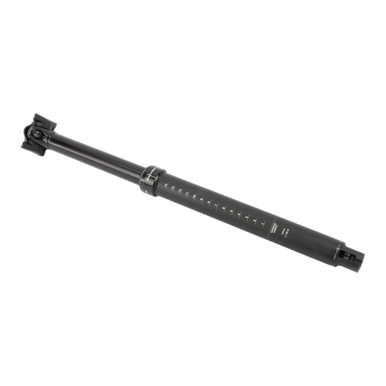
POST-MODERNE
DROPPER SEATPOST
Model No. PM-MT171
CONTACT US / INQUIRIES:
Web: www.postmoderne.com
Email: pm-info@postmoderne.com
Mail:
Post Moderne
Moderne Tech Corporaton
No.367 Kao-Shih Road
Yangmei, Taoyuan 326
Taiwan, R.O.C.
SERVICE & REPAIR INSTRUCTIONS
Please refer to Dimensions / Specifcatons / Parts /
Kits listed on opposite page.
⚠
WARNING:
Seat post Drop (dimension D) is specifc to the length
of the Length (dimension L2). Only use the
combinatons of the same drop spec of cartridge
(dimension L3) with the specifc Upper Tube
(dimension L4) and Lower Tube (dimension L5).
⚠
CAUTION:
All bicycle maintenance and installaton should be
installed by a qualifed bicycle service technician or
mechanic, in accordance with the manufacturer's
installaton specifcatons. If you are not fully qualifed
or experienced in the feld of bicycle maintenance,
then defer to a professionally trained bicycle service
technician or mechanic.
⚠
WARNING:
Improperly installed products are at risk to fail
suddenly and/or unexpectedly, causing the rider to
lose control, potentally causing SERIOUS INJURY OR
DEATH.
⚠
CAUTION:
Do not clamp your bike in a work stand by any part of
the seatpost's upper tube.
TOOLS REQUIRED:
Allen Keys: 2.5mm, 5mm, 10mm
Post-Moderne Nut Tool
Torque Wrench
Grease (suitable for stanchions, such as Finish Line™
Teflon or uuzzy's Slick Honey™)
DISASSEMBLY
Follow these steps to disassemble the seatpost.
1. Raise the seatpost to full height by releasing the
Remote Trigger.
2. uefore removing the seatpost, make notes of: (i)
seatpost height in the seat tube, (ii) saddle fore-af
positon and tlt angle.
3. Remove the seatpost from the frame's seat tube.
4. If there is not enough slack in outer-housing of the
remote-release cable then either un-bolt the remote-
release from the handlebar or un-clamp the inner-
cable from the remote-release.
5. When the seatpost clears the seat-tube then un-
hook the cable nipple from the recess in the actuator
Post Moderne PM-MT171 Service Sheet - Rev.20180208
assembly at the botom of the seatpost. At this point,
the seatpost should be un-tethered from the bike.
6. Use a 5mm allen key to loosen or remove the rear
screw (part (D6)) of the saddle clamp assembly.
7. When the set-screw underneath is accessible, then
loosen it with a 2.5mm allen key.
8. With a 10mm allen key, unscrew the actuator
assembly (part (F3)) from the botom of the lower-
tube, along with the damper cartridge (part (A1)).
9. Using the special Lock Nut Tool (part (F2)), slide the
tool into the Actuator Assembly to remove the
Damper Cartridge assembly.
10. uy hand, unscrew the Collar Ring (part (E1)) from
the Lower Tube and separate the Lower Tube from the
Upper Tube.
11. Separate the Lower uushing (part (E4)), Slot Keys
(2pcs of part (E3)), Upper uushing (part (E2)) and
Collar Ring.
12. At this point, the seatpost is entrely dis-
assembled.
13. Clean and inspect each part and sub-assembly.
14. If any parts are worn or damaged, then order the
replacement parts which are available in the Service
Kits (A, u, C, D, E and F) listed on the opposite page.
REASSEMBLY
Follow these steps to re-assemble the seatpost.
15. uefore sliding the Collar Ring back onto the Upper
Tube, wrap the Plastc Film for Assembly (part (E5))
around the lower end of the Upper Tube. This step is
important to protect the sof Wiper Seal from being
damaged by the sharp machined edges that retain the
Lower uushing and Slot Keys.
16. Slide the Collar Ring over the Plastc Film and far
onto the Upper Tube, past the sharp edges.
17. Slide the Upper uushing onto the Upper Tube, past
the keyways.
18. Carefully slide the Slot Keys into the keyways. Start
from the botom and slide them in longitudinally. Do
not try to press them in laterally.
19. Insert the Lower uushing by frst lining it up so that
it aligns with the keyways. Then when it is in positon,
rotate it 90° to lock into place.
20. Grease the Upper and Lower Tubes liberally
between the bushings and below the wiper seal.
21. Insert the greased Lower-Tube into the Upper
Tube. Make sure that the bushings and keys are in-
place before insertng.
22. uy hand, screw the Collar Ring tghtly onto the
Lower Tube.
23. Insert the tube end (fat end) of the Damper
Cartridge through the botom of the seatpost. Align
the flat spot of the nub at the top with the set-screw
at the top of the seatpost. Tighten the set-screw with
a 2.5mm allen-key to 2.0 N-m.
24. uy hand, thread the Actuator Assembly onto the
Cartridge Lock Nut.
25. With a 10mm allen key, thread the Actuator
Assembly fully into the botom of the Lower Tube. The
assembly should be botom out, but should not be
over-tghtened. Torque to 50 N-m.
26. At this point, the saddle clamp assembly can be re-
tghtened and the saddle positon re-set.
27. The nipple-end of the remote-release inner-cable
should be inserted into the recess in the actuator
assembly at the botom of the post.
28. Re-install the seatpost into the frame's seat-tube.
> For aluminum or steel frames: Apply a thin coatng
of grease to the seatpost's external tube.
> For carbon fbre frames: Apply a thin coatng of
fricton paste (instead of grease) to the seatpost's
external tube.
Tighten the seatpost into the frame, using the
clamping mechanism on the frame tghtened to the
frame manufacturer's specifcaton.
29. Reconnect the cable and/or remote-release at the
handlebar and remove any excess slack from the
inner-cable.
30. Check the Remote Release. Sitng on the saddle,
depress the remote release. If the saddle does not
drop, then increase the cable tension by opening the
barrel adjuster on the release and/or pulling more
cable through the cable-clamp.
Next, unweight the saddle. If the saddle does not
extend to full height, then decrease the cable tension
by closing the barrel adjust on the release and/or
letng out more cable through the cable-clamp.
Repeat the above steps to re-check the drop and
extension.
Advertisement
Table of Contents

Related Manuals for POST-MODERNE PM-MT171

Summary of Contents for POST-MODERNE PM-MT171
- Page 1 Tighten the set-screw with a 2.5mm allen-key to 2.0 N-m. 5. When the seatpost clears the seat-tube then un- hook the cable nipple from the recess in the actuator Post Moderne PM-MT171 Service Sheet - Rev.20180208...
Need help?
Do you have a question about the PM-MT171 and is the answer not in the manual?
Questions and answers