Table of Contents
Advertisement
Quick Links
Model Numbers:
IDV24 - Stock Numbers: IDV24N, IDV24NE, IDV24NE2, IDV24LP, IDV24LPE, IDV24LPE2
Minimum Fireplace Opening Required: 24-1/4"W x 18-1/2"H x 14"D
Are Certified to: CSA/ANSI Z21.88:19 • CSA 2.33:19 and CSA2.17-2017
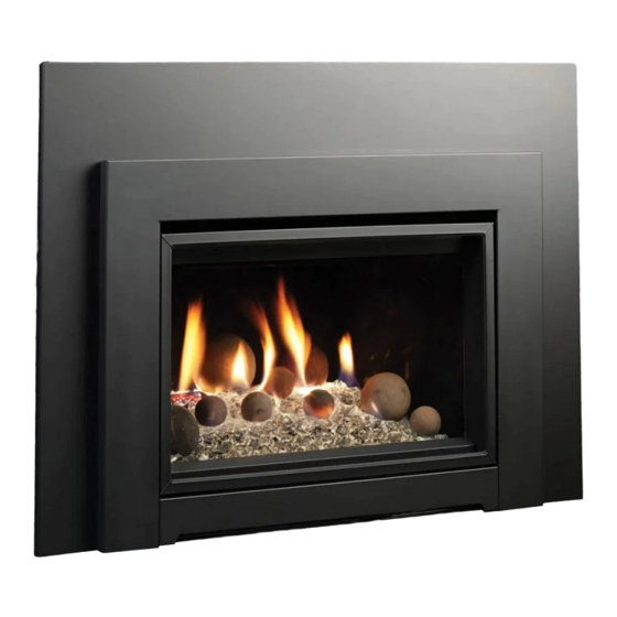
VENTED GAS FIREPLACE HEATERS
Installation Instructions
Gas Fireplace Insert Heater
Listed Certified for USA. and Canada
This appliance may be installed in an aftermarket,
permanently located, manufactured home (USA
only) or mobile home, where not prohibited by
This appliance is only for use with the type of
gas indicated on the rating plate. This appliance
is not convertible for use with other gases,
unless a certified kit is used.
⚠
WARNING: The IDV24 Fireplace Insert was
designed for installation in a solid fuel fireplace
that has been installed in accordance with
national, provincial / state and local building
codes and is constructed of noncombustible
materials. Do not remove any refractory materials
from any masonry solid fuel fireplace.
The IDV24 Fireplace Insert was designed for
installation in a zero-clearance type listed solid fuel
burning factory-built fireplace. It may be necessary to
remove the damper plate, refractory liners, log grates,
glass door, and screen rails/mesh. Removal of the
smoke baffle is necessary in most cases.
INSTALLER: Leave this manual with the
appliance.
CONSUMER: Retain this manual for
future reference.
VENTED GAS FIREPLACE HEATER:
NOT FOR USE WITH SOLID FUEL.
CAPRI
local codes.
A Division of R-Co. Inc.
2340 Logan Avenue
Winnipeg, Manitoba, Canada R2R 2V3
Ph: (204) 632-1962
Printed in Canada September 6, 2022
Part # 24IDV-MAN19
Advertisement
Table of Contents

Summary of Contents for Kingsman Fireplaces IDV24
- Page 1 Gas Fireplace Insert Heater Listed Certified for USA. and Canada Model Numbers: IDV24 - Stock Numbers: IDV24N, IDV24NE, IDV24NE2, IDV24LP, IDV24LPE, IDV24LPE2 Minimum Fireplace Opening Required: 24-1/4”W x 18-1/2”H x 14”D Are Certified to: CSA/ANSI Z21.88:19 • CSA 2.33:19 and CSA2.17-2017...
-
Page 2: 24Idv - Table Of Contents Important Information / Glass Safety
Important Information INSTALLATIONS • The following label (supplied with the gas fireplace insert) must be attached with rivets or screws to the inside of the firebox of the fireplace into which it is installed: • Cutting any sheet-metal parts of the fireplace, in which the gas fireplace insert is to be installed, is prohibited. •... -
Page 3: Table Of Contents
IDV24 Mantel Heights..............................Wall Coverings, Side Walls, and Hearth Requirements..................... Using Steel Studs and Concrete Board........................Leveling Instructions…………............................. IDV24 - Riser Kit Installation Instructions – Model No.: I34R40………………………………………………………….. Surround Installations..............................Clean View Attachment.............................. Media and Accessories I33CS Mantel Clearance Shield Instructions……………………………………………………………………………….. - Page 4 47-48 Proflame 2 Schematic..............................WMBH – Wall Mount Battery Holder – Proflame 1 and 2 IPI Models……………………………………………………. Venting IDV24 Venting Installation…………………………………………………………………………………………………….. IDV24 Vent Pipe Installation............................Insulation of Chimney Cavity............................IDVVT32-KIT 2/3 Venting Adapter Kit………………………………………………………………………………………. Parts List IDV24 Parts List................................. 55-56...
-
Page 5: Safety Screen Installation
Safety Screen Installation - IDV24 I24CSS SAFETY SCREENS ARE SUPPLIED IN I24CV1BL Kits ⚠ WARNING: Wait until unit is COMPLETELY cool before touching glass or attempting to install or remove Child Safety Screens. To Install SLOT Screen: Insert Hooks on Safety... -
Page 6: Pre-Installation Questions And Answers
Pre-installation Questions and Answers About curing of the paint Your stove or fireplace has been painted with the highest quality silicone stove paint. This paint dries quickly in 15-20 minutes when first applied at the factory. However, due to the high temperature silicone components, the paint will cure when heat is applied to the appliance as it is first used. -
Page 7: Warnings, Installations And Operations
Warnings, Installations and Operations - Installation Regulations This gas appliance must be installed by a qualified installer in accordance with local building codes, or in the absence of local codes, with the current CAN/CSA-B149.1 or .2 Installation Code (in Canada) or the current National Fuel Gas Code Z223.1- NFPA 54 when installed in the United States. -
Page 8: Installation Requirements For The Commonwealth Of Massachusetts
Installation Requirements for the Commonwealth of Massachusetts In the Commonwealth of Massachusetts, the installer or service agent shall be a plumber or gas fitter licensed by the Commonwealth. When installed in the Commonwealth of Massachusetts or where applicable codes; the unit shall be installed with a CO detector per the requirements listed below. -
Page 9: Mobile Home/Manufactured Housing Installation
Mobile Home/Manufactured Housing Installation This Direct Vent System Appliance must be installed in accordance with the manufacturer’s installation instructions and the Manufactured Home Construction and Safety Standard Title 24 CFR, Part 3280, or the current Standard for Fire Safety Criteria for Manufactured Home Installation, Sites, and Communities ANSI/NFPA 501A, and with CAN/CSA Z240 MH Mobile Home Standard in Canada. -
Page 10: Idv24 Fireplace Openings
IDV24 Fireplace Openings REQUIRED DIMENSION A Front Width 24-1/4” B Height 18-1/2” C Depth 14” “D” “C” D Back Width 19-1/4” “B” “A” IDV24 Fireplace Dimensions FRONT LEFT SIDE... -
Page 11: Idv24 Clean Views And Surround Options
IDV24 - Clean View and Surround Options I24CV1BL I24CV1BL with I24S3827 Surround I24CV1BL with I24S3827 Surround, I34R40 Riser, I33CS Mantel Clearance Shield I24CV1BL with I24SPF3829 Picture Frame Surround I24CV1BL with I24SU4541 Universal Surround... -
Page 12: I24Su4541 -Universal Surround- Idv24
I24SU4541 -Universal Surround- IDV24 For use with I24CV1BL. This Surround can be custom cut and bent. NOTE: If you wish to make the bottom of the surround flush with the fireplace bottom, cut surround at dotted line. The Surround Ledge can be removed by drilling out the three rivets. -
Page 13: Idv24 Mantel Heights
IDV24 Mantel Heights IDV24 Combustible Mantel Heights I24CV1 Only I24CV1 with Mantel or with Surround and I33CS Dimension Depth Surround Mantel Shield 0” 31-1/8” 31-1/8” 2” 33-1/8” 33-1/8” 4” 35-1/8” 35-1/8” 6” 37-1/8” 37-1/8” 8” 39-1/8” 39-1/8” 10” 41-1/8” 41-1/8”... -
Page 14: Wall Coverings, Side Walls, And Hearth Requirements
IDV24 – Wall Coverings, Side Walls and Hearth Requirements Refer to Mantel Heights Chart for detailed information. Combustible Mantel Line Floor beneath appliance must be 12” NON- non-combustible. COMBUSTIBLE AREA ABOVE FIREPLACE SIDE WALL CLEARANCE TO COMBUSTIBLES 1/2” MIN Clearance... -
Page 15: Leveling Instructions
Replace screws. Right Side View Leveling Leg Measure Leveling Legs Height IDV24 - Riser Kit Installation Instructions – Model No.: I34R40 Measure the height required and set the Riser Supports. Slots in Fireplace Bottom Locate slots at bottom front of unit. -
Page 16: Surround Installations
IDV24 – Surround Installation IDV24 Surrounds: I24S3827, I24SPF3829, 124SU4541 PARTS LIST: -Surround All surrounds attach to the back of the Clean View. - [Qty 9] #6 Black Screws Surround Attachment: STEP 1: Place Surround against back Surround of Clean View... -
Page 17: Clean View Attachment
IDV24 Clean View Attachment Parts List: NOTE: Vent adapter and venting must be connected to the unit before Clean Views -I24CV1BL Clean View and Surrounds are attached. Refer to Installation of Vent Pipe section of this manual for -Safety Screen venting information. -
Page 18: I33Cs Mantel Clearance Shield Instructions
I33CS Mantel Clearance Shield Instructions Option Contents of Kit: [1] Mantel Clearance Shield c/w Screws Place I33CS upside down on a protected surface. Loosen screws. Center surround onto I33CS. Tighten screws to hold surround in place. Surround is now ready to install onto Clean View. -
Page 19: Idv24Rlt Brick Liner Panels
IDV24RLT Brick Liner Installation Option Parts List -1 Back Panel -1 Right Side Panel -1Left Side Panel Installation 1. Remove Brick Clips from sides of firebox. 2. Install the Back Panel. 3. Carefully slide and tilt Side Panels into place. 4. -
Page 20: Logf24Dw Driftwood Log Setup
IDV24 LOGF24DW Driftwood and LOGF24OAK Oak Log Setup Option ⚠ WARNING: Failure to position the parts in accordance with these diagrams or failure to use only parts specifically approved with this appliance may result in property damage or personal injury. -
Page 21: Crushed Glass And Media Options
IDV24 Crushed Glass and Media Options - MQ Dealers Only - IDV24 requires [Qty 2] 5LB bags of crushed glass. All glass is sold in 5 LB bags (Maximum 10 LBS of Glass). GLASS SKU DESCRIPTION GLASS (MQG5W, MQG5A, MQG5B, MQG5ZG, MQG5C) Decorative Glass 1/2”... -
Page 22: Mqrock2, Mqrock3
IDV24 - Marquis Collection - Options MQROCK2, MQROCK3- MAXIMUM 21 PIECES CAN BE USED. • Lava Rock is supplied with Base Unit. Do not place directly onto Burner. • Place rocks randomly onto False Bottom and Burner. Do not place directly on burner ports. -
Page 23: Mq Ember Installation
IDV24 - Marquis Collection - Options • MQEMBER • To be placed directly on Burner and Burner Ports. • Place these glowing ember chunks randomly. May be used with or without other accessories. RBCB1 Cannonballs – DO NOT USE LARGE CANNONBALLS Assorted size and colors. -
Page 24: Fan Removal / Installation
IDV24 Fan Removal / Installation ⚠ WARNING Before Servicing: Ensure all power supply is shut off. Electrical Grounding Instructions Label all wires prior to disconnecting when servicing control. This appliance is equipped with a three prong (grounding) plug Wiring errors can cause improper and dangerous operation. -
Page 25: Halogen Lights- P2 Models Only
IDV24 Halogen Lights- Proflame 2 Units- Factory Installed Please follow the current ANSI/NFPA 70 National Electrical Code in the USA and CAN/CSA C22.1 Canadian National Electrical Code in Canada. Components: • Lamp Plate with insulated studs & wiring • 12VAC Transformer with wire connectors •... -
Page 26: Glass Door Information / Door Installation And Removal
Latch Pull Bottom Latch Bottom Door Ledge IDV24 Glass Door Removal and Installation To Disengage Top Latch: 1. Disengage Top Latches by pulling on Latch Pull with one hand and pushing up on Latch Pull with the thumb of your other hand (See Photo to left). -
Page 27: Gas Section Burner Removal / Burner System Removal / Installation
IDV24 Burner Removal To remove Burner, remove Pilot Shield, Ember Plates, Burner Pilot Shield Glass Fences, and Burner Retainers. Glass Fence Slide Burner slightly to the left to dislodge it from the Orifice and remove it from the fireplace. -⚠... -
Page 28: Burner System Maintenance
IDV24 Burner System Maintenance It is recommended to annually inspect and clean the Burner System to prevent malfunction and / or sooting. This operation should be performed by your dealer or a qualified technician. ⚠ -CAUTION- Before servicing the burner system ensure that the gas supply is turned OFF and disconnect all electrical connections to the appliance. -
Page 29: Conversion Kit Instructions - Part A
IDV24 -Gas Conversion Part A- IDV24N, IDV24NE, IDV24NE2, IDV24LP, IDV24LPE, IDV24LPE2 Burner Orifice Kit Number Description Pilot Orifice Brass (1000-255) Brass Nipple Air Shutter Hi/Lo Regulator Propane Conversion 1001-P167SI 1000-P201VE 1001-P202SI 24IDV-CKLP Fully Open -Millivolt- #30 (977.167) (0.907.202) NG Conversion... -
Page 30: Gas Conversion For Sit Top Convertible Pilot - Part B
Gas Conversion for Top Convertible Pilot – Part B (series 0190XYZ) Instructions for converting SIT 190 series pilot burner injector from NG to PROPANE and from PROPANE to NG only. This information should be considered as supplemental to the Appliance Manufacturer's Instructions. -
Page 31: Gas Conversion For Sit Modulator - Part C
Gas Conversion for Modulator – PART C... -
Page 32: Gas Line Installation / Gas Specifications
Gas Line Installation This gas appliance should be installed by a qualified installer in accordance with local building codes and with current CAN/CSA - B149.1 installation codes for Gas Burning appliances and equipment in Canada and the National Fuel Gas Code ANSI Z223 in the U.S.A. -
Page 33: Millivolt System, Lighting, And Burner Control
Millivolt System, Lighting, and Burner Control FOR YOUR SAFETY READ BEFORE LIGHTING WARNING: If you do not follow these instructions exactly, a fire or explosion may result causing property damage, personal injury or loss of life. BEFORE LIGHTING Immediately call your gas supplier from a neighbour’s phone. Follow the This appliance has a pilot which must be lighted by hand. -
Page 34: Lighting Instructions For Millivolt Valve With 7 Day Timer
- Lighting Instructions for Millivolt Valve with 7 Day Timer - FOR YOUR SAFETY READ BEFORE LIGHTING WARNING: If you do not follow these instructions exactly, a fire or explosion may result causing property damage, personal injury or loss of life. •... -
Page 35: Ipi Lighting Instructions
- IPI LIGHTING INSTRUCTIONS - FOR YOUR SAFETY READ BEFORE LIGHTING WARNING: If you do not follow these instructions exactly, a fire or explosion may result causing property damage, personal injury or loss of life. • This appliance is equipped with an ignition device which If you cannot reach your gas supplier, call the fire automatically lights the pilot. -
Page 36: Annual Inspection List For Determining Safe Operation Of A Direct Vent Gas Fireplace
Annual Inspection List for Determining Safe Operation of a Direct Vent Gas Fireplace Refer to this checklist for proper maintenance, safe use, and operation. See each section for more specific information. 1. Inspect and operate all pressure relief mechanisms (i.e., relief dampers, spring loaded door latches) installed on your appliance to verify relief mechanisms are free from obstruction to operate. -
Page 37: Troubleshooting The Gas Control System
Troubleshooting the Gas Control System ⚠ WARNING BEFORE DOING ANY GAS CONTROL SERVICE WORK, REMOVE THE GLASS FRONT. NOTE: Before troubleshooting the gas control system, be sure external gas shut off is in the "On" position. Problem Possible Causes Corrective Action Spark igniter will not Defective or misaligned Check for spark at electrode and pilot: if no spark and electrode wire is... -
Page 38: Overview / Components
24IDV - Proflame 1 IPI Electronic Ignition System Overview The IPI system is an advanced burner controller that provides you with Box Cover the option of having either a Standing-Pilot, or an intermittent igniting system. This alternating mode is controlled by the CPI/IPI Switch (Continuous Pilot Ignition/Intermittent Pilot Ignition) located on the IPI System Box. -
Page 39: Junction Box Location
IPI Electronic Ignition System NOTE: The Remote Receiver module can also be located outside of the appliance to a maximum of 6ft away installed in a certified deep wall switch electrical box (2-3/4” depth). For this configuration an extension wiring harness (P/N: 1001-P904SI) is required. Electrical Supply in Series: The entire IPI system can be powered by a single power source (i.e. -
Page 40: Ipi Proflame 1 -Remote Control Operation
IPI Proflame 1 -Remote Control Operation- The Proflame GTM is configured to control the on/off main burner operation, its flame levels, and provides on/off and Smart *thermostatic control of the appliance. Transmitter Remote Receiver Transmitter Room *thermostat ( Transmitter Operation) The Transmitter is powered by 3 AAA type batteries. -
Page 41: Ipi Electronic Ignition Parts List - Standard System
Proflame 1 -IPI System Parts List- PART NO. DESCRIPTION 1006-P002SI Valve IPI Hi/Lo NG 11. 1002-P012SI IPI Stepper Kit - LP 907.012 1006-P003SI Valve IPI Hi/Lo LP 12. 1002-P013SI IPI Stepper Kit - NG 907.013 1002-P302SI IPI Ignition Board 13. 1002-P014SI IPI Reg Kit - LP Hi-Lo 907.014 Pilot Assembly-LP -24”... -
Page 42: Configuration1 / Configuration 2
Configuration #1: Basic manual HI/LO and manual ON/OFF capabilities. 1001-P221SI Configuration #2: Remote ON/OFF and Manual HI/LO Capabilities OPTIONAL: For units with remote HI/LO capabilities, a modulating servo is required to be installed on the valve. The connectors to this servo must be connected to the Remote Harness as shown. -
Page 43: Operating The Receiver Without Batteries For Gt / Egt / Gtm / Egtm Remote Controls
Operating the Receiver Without Batteries for GT / EGT / GTM / EGTM Remote Controls -Wiring Harness P/N 1002-P906si required for both IPI & Millivolt systems. -Millivolt Systems will also require Power Adapter P/N 1002-P850si. The Remote Receiver & IPI or Millivolt system can be powered by the AC Adapter. This is advantageous if you do not want to use batteries. -
Page 44: Proflame 2 Ipi Proflame 2- Parts List
Proflame 2 –NE2 / LPE2 -IPI System Parts List- IPI PROFLAME 2 - COMPONENT PARTS IPI - PF1 and PF2 Common Components PART NO. DESCRIPTION PART NO. DESCRIPTION 1005-P001SI Valve IPI Proflame PF2 885.001 NG - Stepper 13. 1002-P033SI TC - Pilot Burner IPI (Assembled) NG 199.033 1005-P002SI Valve IPI Proflame PF2 885.002 LP - Stepper 14. -
Page 45: Proflame 2 Ifc Module And Remote Control
IPI Proflame 2 IFC Module and Remote Control Batteries IFC Module Button remain on CPI (continuous pilot ignition) mode, all Pairing Remote Control: other functions of main burner, fan and lights will be • Install the 3 AAA type batteries in the battery bay, on the high setting. -
Page 46: Cold Climates - Cpi Setting
Cold Climates – CPI Setting - Proflame 2 Remote Control Use the CPI setting during cold weather, otherwise the fireplace may have a hard time starting up and establishing a flame. The CPI (Continuous Pilot Ignition) setting will keep the firebox and fireplace exhaust vent warm during cold weather. -
Page 47: Proflame 2 Remote Control Operation
Proflame 2 Remote Control... - Page 48 Note: When Smart Thermostat is activated, manual flame height adjustment is disabled. (Halogen lights only) Note: This function is only available in Room Thermostat or Smart Thermostat Control Mode.
-
Page 50: Wmbh - Wall Mount Battery Holder - Proflame 1 And 2 Ipi Models
WMBH – Wall Mount Battery Holder – Proflame 1 and 2 IPI Models - Option The WMBH provides the option for a more convenient and accessible location for the backup batteries. NOTE: The WMBH is NOT a remote control receiver. It functions as a Battery Holder and mode selector switch ONLY. - NOT FOR USE WITH POWER VENTS - Parts List: [1] Battery Holder... -
Page 51: Venting Idv24 Venting Installation
IDVFK25 Max. 40ft [12.2m] 2ft [0.6m] screws.) For use with the IDV24 fireplace when I23FAK-KIT venting must pass through a 6-inch chimney. ⚠ WARNING: Failure to position the parts in accordance with these diagrams or failure to use only parts specifically approved with this appliance may result in property damage or personal injury. -
Page 52: Idv24 Vent Pipe Installation
IDV24 Vent Pipe Installation Follow this procedure in order to ensure a tight connection between the gas fireplace insert, the adapter plate, and the vent pipes. 1. Attach the vent pipes to the termination with Millpac and 4 screws per pipe joint. Be sure to label the exhaust and intake flex pipes. -
Page 53: Insulation Of Chimney Cavity
IDV24 Chimney Cavity Insulation If You Live In A Cold Climate Zone And Your Chimney Is On The Side Of Your House In cold climates, especially where the chimney is located on the outside of the home it may be necessary to insulate the chimney cavity with NON-COMBUSTIBLE insulation such as vermiculite or Roxul insulation. -
Page 54: Idvvt32-Kit 2/3 Venting Adapter Kit
I23FAK-KIT Flue Adapter Kit Option For use with the IDV24 fireplace when venting must pass through a 6-inch chimney. I23FAK-KIT Parts List: [Qty 2] 2 to 3 Inch Adapters 3” Flex 2” Flex [Qty 1] 6 to 7 Inch Adapter... -
Page 55: Idv24 Parts List
WI-FI Dongle and Harness Kit - for Proflame 2 Appliances (Control OTHER ACCESSORIES your fireplace with your smartphone - 2-1/2” Riser 40” I34R40 App required) I33CS Mantel Clearance Shield REPLACEMENT BURNER ASSEMBLY / BURNER 24IDV-200A H-Burner (For use on IDV24 only) - Page 56 OFP42SA Spark Assist (Millivolt) FP15GC Stainless Steel Gas Connector 24IDV-BN Millivolt Burner Assembly- Natural Gas c/w Valve System PARTS FOR IDV24 VENTING Vertical Termination – Collinear IDVVT36 24IDV-BLPE Proflame 1 Burner Assembly- 3”/3” Propane c/w Valve System 3” Diameter [2Ea] Unexpanded...
-
Page 57: Limited Lifetime Warranty
This Limited Lifetime Warranty applies only while the unit remains at the site of the original installation and only if the unit is installed inside the continental United States, Alaska, Hawaii, and Canada. The warranty applies only if the unit is installed and operated in accordance with the printed instructions and in compliance with applicable installation and building codes and good trade practices.
Need help?
Do you have a question about the IDV24 and is the answer not in the manual?
Questions and answers