Table of Contents
Advertisement
Quick Links
Advertisement
Table of Contents

Related Manuals for Power Solid PSiO60000W3 1100VPVK

Summary of Contents for Power Solid PSiO60000W3 1100VPVK
- Page 3 Notice The purchased products,services and features are stipulated by the contract made between the customer. All or part of the products, services and features described in this document may not be within the purchase scope or the usage scope. Unless otherwise specification in the contract, all statements,information, and recommendations in this document are provided “AS IS”...
- Page 4 Grid-tied Inverter Foreword User Manual Foreword Summaries Thank you for choosing the PSiO60000W3#1100VPVK PV grid-tied inverter(Hereinafter referred to as inverter)! This document gives a description of inverter, including the appearance, features, working principles, installation, electrical connection, operation, maintenance and storage, etc. Please save the manual after reading, in order to consult in the future.
- Page 5 Grid-tied Inverter User Manual Foreword Symbol Description Alerts you to a high risk hazard that could, if not avoided, result in serious injury or death. Alerts you to a medium or low risk hazard that could, if not avoided, result in moderate or minor injury. Alerts you to a potentially hazardous situation that could, if not avoided, result in equipment damage, data loss, performance deterioration, or unanticipated results.
-
Page 6: Table Of Contents
Grid-tied Inverter Contents User Manual Contents 1 Safety Description......................... 1 1.1 Safety Announcements ............................. 1 1.1.1 Use Announcements ..........................1 1.1.2 PV Array Protection ..........................3 1.1.3 ESD Protection ............................3 1.1.4 Grounding Requirements ........................4 1.1.5 Moistureproof Protection ........................ - Page 7 Grid-tied Inverter User Manual Contents 3.2 Installation Preparation ..........................14 3.2.1 Installation Tools ........................... 14 3.2.2 Installation Environment ........................15 3.2.3 Installation Clearance ..........................15 3.3 Handling, Unpacking and Checking ......................16 3.3.1 Handling ..............................16 3.3.2 Unpacking and Checking ........................
- Page 8 Grid-tied Inverter Contents User Manual 6.1 Maintenance ..............................61 6.2 Troubleshooting .............................. 61 7 Package,Transportation,Storage ....................65 7.1 Package ................................65 7.2 Transportation ..............................65 7.3 Storage ................................65 A Technical Specifications ......................66 ...
-
Page 9: Safety Description
Grid-tied Inverter User Manual 1Safety Description 1 Safety Description This chapter mainly describes the safety announcements.Prior to performing any work on the device, please read the user manual carefully, follow the operation and installation instructions and observe all danger, warning and safety information, which is to avoid human injury and device damage by irregular operations. - Page 10 Grid-tied Inverter 1Safety Description User Manual There is no operational part inside device. Please do not open the crust of device by yourself, or it may cause electric shock. The device damage caused by illegal operation is out of the guarantee range.
-
Page 11: Pv Array Protection
Grid-tied Inverter User Manual 1Safety Description No liquid or other objects are allowed to enter the cabinet. In case of fire, please use dry power fire extinguisher. If using liquid fire extinguisher, it may cause electric shock. 1.1.2 PV Array Protection When install PV array in daytime, it necessary to cover PV array by light-proof material, or the PV array will generate high voltage under sunshine. -
Page 12: Grounding Requirements
Grid-tied Inverter 1Safety Description User Manual 1.1.4 Grounding Requirements High leakage risk! Device must be grounded before performing electrical connection. The grounding terminal must be connected to ground. When install device, it must be grounded first. When dismantle device, the grounding wire must be removed at last;... -
Page 13: Measurement Under Operation
Grid-tied Inverter User Manual 1Safety Description The configuration of PV array, grid level, grid frequency, etc. must meet the technical requirements of inverter. Grid-tied generation should be allowed by the local power supply department and the related operation should be performed by professionals. All electrical connection must meet the related country and district standard. -
Page 14: Operation Environment Requirements
Grid-tied Inverter 1Safety Description User Manual Operator must be familiar with the related country and district standard. 1.3 Operation Environment Requirements The operation environment may influence the life span and reliability of device. So, please avoid to use device in following environment: ... -
Page 15: Overview
Grid-tied Inverter User Manual 2Overview 2 Overview This chapter mainly describes product introduction, components and working principle, etc. 2.1 Product Intro The inverter converts the DC energy from PV array into AC energy and then feedbacks to power grid, which is suitable for the commercial roof grid-tied system and large power station grid-tied system. The PV grid-tiedgeneration system consists of PV array, PV grid-tied inverter, transformer(According to practical application) and power distribution system, as shownFigure2-1. -
Page 16: Features
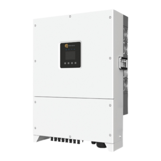
Grid-tied Inverter 2Overview User Manual Figure2-2 Appearance 2.1.2 Features Adopts the efficient type-T three level high frequency conversion technology and advanced full digital control technology. Adopts the advanced disturbance detection technology to realize the anti-island running protection. Equipped with perfect protection function and the nighttime loss is low. ... - Page 17 Grid-tied Inverter User Manual 2Overview Figure2-3 Grid mode...
-
Page 18: Compoments
Grid-tied Inverter 2Overview User Manual In the TT grid mode, the rms voltage between the neutral wire and grounding wire must be less than 20V. If the inverter is equipped with anti-PID module SPID-S, it only can select IT grid mode. Besides, it need to configure transformer. -
Page 19: Dc Switch
Grid-tied Inverter User Manual 2Overview Type Mark Color Meaning Status Illustration indicator No grid-tied status WIFI/ GPRS has been connected WIFI/GPRS Green indicator WIFI/ GPRS has been disconnected Fault indicator The inverter has protection action. Button There are four buttons on the front panel of inverter, the button function is as shown in Table2-2. Table2-2 Button function Button Function... -
Page 20: Working Principle
Grid-tied Inverter 2Overview User Manual Figure2-5 DC switch When maintenance or wiring, it should switch off DC switch. 2.3 Working Principle PV array input connected with inverter, which will combine into n routes of MPPT circuits inside the inverter to do the max. power point tracking. Then convert the DC power into three-phase AC power through inverting circuit and support the surge protection in the DC side and AC side, the details refer toFigure2-6. -
Page 21: Installation
Grid-tied Inverter User Manual 3Installation 3 Installation This chapter mainly introduces the inverter's installation, including installation process, installation preparation, handling, unpacking and checking, installation procedures, electrical connection. check the installation ,etc. 3.1 Installation Process The installation process of inverter is as shown in Figure3-1. Figure3-1 Installation process... -
Page 22: Installation Preparation
Grid-tied Inverter 3Installation User Manual 3.2 Installation Preparation 3.2.1 Installation Tools Tools... -
Page 23: Installation Environment
Grid-tied Inverter User Manual 3Installation Tools 3.2.2 Installation Environment The installation environment of inverter should meet the following items: Do not install the inverter in the place with poor ventilation. There has sufficient fresh-air supply around the inverter. ... -
Page 24: Handling, Unpacking And Checking
Grid-tied Inverter 3Installation User Manual Figure3-2 Installation clearance 3.3 Handling, Unpacking and Checking 3.3.1 Handling The inverter should be handled to the installation site by trained professionals(at least two person). -
Page 25: Unpacking And Checking
Grid-tied Inverter User Manual 3Installation When handling device, move it carefully to avoid impact or fall. When handling device, keep it vertical. Don't put it down or put it up suddenly. 3.3.2 Unpacking and Checking Determine the unpacking site in advance. Normally, it's better that the unpacking site is close to installation position. - Page 26 Grid-tied Inverter 3Installation User Manual Figure3-3 The dimensions of installation holes of installation holder(Unit: mm) Vertical installation is perfect. If it should be tilt, the vertical gradient should not exceed ±15°. The installation procedures are as follows: Step 1 Determine the installation site according to the dimensions of inverter(as shown in Figure3-4) and installation clearance requirements(as shown in Figure3-2).
- Page 27 Grid-tied Inverter User Manual 3Installation Step 2 According to the dimensions of installation holes of installation holder(as shown in Figure3-3), mark the position of installation holes on the wall. Drill holes on the wall vertically by hammer drilling according to the marked position. Keep the installation holder horizontal to ensure that the installation holes on the wall are aligned.
- Page 28 Grid-tied Inverter 3Installation User Manual Figure3-6 Fix the installation holder on the wall Step 5 As shown in Figure3-7, uplift the inverter and insert the holes in the back of the inverter into the bulge of installation holder(total two positions) slowly. It can't release the inverter until it has been fastened firmly.
-
Page 29: Electrical Connection
Grid-tied Inverter User Manual 3Installation Figure3-8 Fasten the inverter ----End 3.5 Electrical Connection The wiring for inverter be performed in the bottom of inverter. The mark is as shown in Figure3-9, and the mark meaning is as shown in Table3-1 The recommended wire requirements is as shown in Table3-2. - Page 30 Grid-tied Inverter 3Installation User Manual 1. PSiO60000W3#1100VPVK have twelve routes of DC input. Table3-1 Mark illustration Mark Illustration PV+ input 1~4 Draw the positive input wires through the PV connectors. PV- input 1~4 Draw the negative input wires through the PV connectors. WIFI/GPRS WIFI/GPRS power supply output port Draw Ethernet communication wire/RS485 communication wire...
- Page 31 Grid-tied Inverter User Manual 3Installation Wire type Specification Recommend Grounding wire 25 mm RNBS22-6...
-
Page 32: Electrical Connection Announcements
Grid-tied Inverter 3Installation User Manual The cables in this table are based on UL copper wire. If other wires are used, please replace them according to the standard. The wire materials selected by our company have passed the national standard certification or UL certification. Refer to Table3-2for the recommended cross-sectional area of the wire when the user purchases the wire by himself (the wire is about 5 meters long).If the wire length exceeds5meters, the cross-sectional area of the wire should be increased accordingly. -
Page 33: Dc Connection
Grid-tied Inverter User Manual 3Installation Figure3-11 The grounding of inverter Step 2 Switch off the DC switch connected with PV array and DC switch in the inverter. Step 3 Connect the DC input in the inverter with the PV array. Step 4 Connect the AC output in the inverter with the grid. - Page 34 Grid-tied Inverter 3Installation User Manual Figure3-12 Positive connector and positive metal terminal Figure3-13 Negative connector and negative metal terminal Step 1 Dismantle the sealing nuts of positive connector and negative connector respectively. Step 2 Strip the insulation layer of positive wire and negative wire for about 7mm by wire stripper, as shown in Figure3-14 and Figure3-15.
-
Page 35: Ac Connection
Grid-tied Inverter User Manual 3Installation Step 5 Insert the positive wire and negative wire into the corresponding insulation crust respectively. If there has a click sound, it means it have been inserted properly. Step 6 Tighten the sealing nuts of positive connector and negative connector to the corresponding insulation crusts respectively. - Page 36 Grid-tied Inverter 3Installation User Manual Figure3-20 Dismantle cover Step 2 Strip the outer insulation jacket of AC wire for about 90mm and the insulation jacket of wire for about 15mm, as show in Figure3-21. Figure3-21 Strip wire If using the hard wires, the stripped length of wire V,W,N can be shorter than wire U, PE for about 5mm to make the wire U, PE connect to connector easily.
-
Page 37: Com. Communication Connection
Grid-tied Inverter User Manual 3Installation Figure3-22 Wiring diagram for AC wire Step 4 After wiring, tighten the nylon cable gland and install the cover. When multiple inverters are in parallel, it's necessary to add breaker with impact tripping function in the AC output backend. - Page 38 Grid-tied Inverter 3Installation User Manual Figure3-23 Dismantle cover Step 2 Loosen the nylon cable gland in the "com."(two pieces) and then draw the communication wires through it. Step 3 Connect communication wire. Ethernet communication connection Crimp Ethernet communication wire according to Figure3-24, and then insert it into Ethernet communication port in the communication board, as shown in Figure3-25.
- Page 39 Grid-tied Inverter User Manual 3Installation Figure3-25 Ethernet communication connection RS485 communication connection Connect RS485 communication wires with RS485 ports in the communication board respectively, as shown in Figure3-26. Connect the other end of RS485 communication wire with computer or logger. Figure3-26 RS485 communication connection When connect with wiring terminals, don't press the insulation layer of communication wires, or it may cause poor connection.
- Page 40 Grid-tied Inverter 3Installation User Manual The communication address and baud rate of inverter can be set by monitor software. The default baud rate is 9600. If any doubt, contact manufacturer. If there has multiple inverters, all inverters can realize the communication connection by communication wires in chrysanthemum chain, as shown in Figure3-27.
-
Page 41: Wifi/Gprs Communication Connection(Optional)
Grid-tied Inverter User Manual 3Installation Figure3-29 DRM communication connection Step 4 After wiring, tighten the nylon cable gland and install cover. ----End 3.5.5 WIFI/GPRS Communication Connection(Optional) If there has optional component WIFI/GPRS stick, insert the equipped WIFI/GPRS stick into the WIFI/GPRS port to do the internet monitoring, as shown in Figure3-30. -
Page 42: Check The Installation
Grid-tied Inverter 3Installation User Manual Figure3-31 WIIF/GPRS monitoring plan 3.6 Check the Installation After installation, check the following items: Check if the connection in the DC input, AC output and communication wire are right. Check if the inverter is installed firmly. Check if all the screws in the crust of inverter are tightened. -
Page 43: Operation Interface
Grid-tied Inverter User Manual 4Operation Interface 4 Operation Interface This chapter mainly introduces the operation interface of inverter. 4.1 Initial Wizard If it's the first time to power on LCD, it will enter the initial wizard. It can set the language, date & time, screen, as shown in Figure4-1 to Figure4-4, the relevant button function is as shown inTable4-1. - Page 44 Grid-tied Inverter 4Operation Interface User Manual Figure4-3 Date & time setting interface Figure4-4 Screen setting interface Table4-1 Button function in the initial wizard interface Button Function Return to the previous level Cancel Quit the selection box ▲ ...
-
Page 45: Main Interface
Grid-tied Inverter User Manual 4Operation Interface 4.2 Main Interface The main interface shows the current status of the inverter, MPPT voltage/ current, grid voltage/ current, output power, daily power generation, CO2 reduction, total power generation and time, etc. Besides, user can query the power generation per hour in histogram, as shown in Figure4-5, the relevant button function is as shown in Table4-2. -
Page 46: Running Information
Grid-tied Inverter 4Operation Interface User Manual Figure4-6 Main menu Table4-3 Button function in the main menu Button Function Quit the main menu ▲ Choose left ▼ Choose right Enter the next level 4.3.1 Running Information In the main interface, press " " button to enter the main menu. In the main menu, press " " button to enter the running information interface, and press "▲"... - Page 47 Grid-tied Inverter User Manual 4Operation Interface Figure4-8 Running information interface (2) Figure4-9 Running information interface(3) Figure4-10 Running information interface(4)
-
Page 48: Power Query
Grid-tied Inverter 4Operation Interface User Manual Figure4-11 Running information interface(5) Table4-4 Button function in the running information interface Button Function Return to the previous level ▲ Page up ▼ Page down 4.3.2 Power Query In the main interface, press " " button to enter the main menu. In the main menu, press "▼" button and then press "... - Page 49 Grid-tied Inverter User Manual 4Operation Interface Figure4-13 Daily power generation query interface(chart) Figure4-14 Daily power generation query interface(figure) Figure4-15 Monthly power generation query interface(chart)
- Page 50 Grid-tied Inverter 4Operation Interface User Manual Figure4-16 Monthly power generation query interface(figure) Figure4-17 Total power generation query interface Table4-5 Button function in the power generation query interface Button Function Return to the previous level Quit the selection box ▲...
-
Page 51: Record Query
Grid-tied Inverter User Manual 4Operation Interface 4.3.3 Record Query In the main interface, press " " button to enter the main menu. In the main menu, press "▼" button twice and then press " " button to enter the record query interface, and press "▲" or "▼" button to view the record information.In the record query interface, you can query the current alarm, history alarm, user log, grid-connected/ off-grid log, power dispatch log and fault wave, as shown in Figure4-18 to Figure4-24, the relevant button function is as shown in Table4-6. - Page 52 Grid-tied Inverter 4Operation Interface User Manual Figure4-21 User log interface Figure4-22 Gird-connected/off-grid log interface Figure4-23 Power dispatch log interface...
-
Page 53: Setting
Grid-tied Inverter User Manual 4Operation Interface Figure4-24 Fault wave list interface Table4-6 Button function in the record query interface Button Function Return to the previous level ▲ Choose upward Page up ▼ Choose downward Page down ... - Page 54 Grid-tied Inverter 4Operation Interface User Manual Figure4-25 Login interface Table4-7 Button function in the login interface Button Function Return to the previous level Quit the selection box ▲ Choose upward Number "+" ▼ Choose downward ...
- Page 55 Grid-tied Inverter User Manual 4Operation Interface Figure4-26 User setting interface Figure4-27 Language setting interface Figure4-28 Screen setting interface...
- Page 56 Grid-tied Inverter 4Operation Interface User Manual Figure4-29 Price setting interface Figure4-30 Password setting interface Table4-8 Button function in the user setting interface Button Function Return to the previous level Quit the selection box ▲ Choose upward Number "+"...
- Page 57 Grid-tied Inverter User Manual 4Operation Interface Administrator setting interface The password of administrator is 200000, as shown in Figure4-31, the relevant button function is as shown in Table4-9 Figure4-31 Login interface Table4-9 Button function in the login interface Button Function ...
- Page 58 Grid-tied Inverter 4Operation Interface User Manual Set the engineer setup according to the practical application and the grid-tied standard, in order to use the default setting. Figure4-32 General setting interface Figure4-33 Communication setting interface Figure4-34 RS485 setting interface...
- Page 59 Grid-tied Inverter User Manual 4Operation Interface Figure4-35 Total power revise interface Figure4-36 Reset password interface Figure4-37 Records management interface...
- Page 60 Grid-tied Inverter 4Operation Interface User Manual Figure4-38 Restore default setting interface Figure4-39 Engineering setup interface(1) Figure4-40 Engineering setup interface(2)
- Page 61 Grid-tied Inverter User Manual 4Operation Interface Figure4-41 Advanced setting interface(1) Figure4-42 Advanced setting interface(2) Figure4-43 PV branch warning mask interface...
- Page 62 Grid-tied Inverter 4Operation Interface User Manual Figure4-44 Grid protect parameter interface(1) Figure4-45 Grid protect parameter interface(2) Figure4-46 Grid protect parameter interface(3)
- Page 63 Grid-tied Inverter User Manual 4Operation Interface Figure4-47 L/HVRT mode parameter interface Figure4-48 L/HFRT mode parameter interface Figure4-49 P-V mode parameter interface...
- Page 64 Grid-tied Inverter 4Operation Interface User Manual Figure4-50 P-F mode parameter interface Figure4-51 Q-V mode parameter interface Figure4-52 SPF mode parameter interface Table4-10 Button function in the administrator setting interface Button Function Return to the previous level Quit the selection box ▲...
-
Page 65: On/ Off
Grid-tied Inverter User Manual 4Operation Interface Button Function Number "+" ▼ Choose downward Number "-" Enter the next level Confirm the selection Select number bit in the selection box Long press to save 4.3.5 ON/ OFF In the main interface, press "... -
Page 66: About
Grid-tied Inverter 4Operation Interface User Manual Table4-11 Button function in the ON/ OFF interface Button Function Return to the previous level Cancel Enter the confirmation interface Confirm 4.3.6 About In the main interface, press " " button to enter the main menu. In the main menu, press "▼" button five times and then press "... - Page 67 Grid-tied Inverter User Manual 4Operation Interface Table4-12 Button function in the about interface Button Function Return to the previous level ▲ Page up ▼ Page down...
-
Page 68: Startup And Shutdown
Grid-tied Inverter 5Startup and Shutdown User Manual 5 Startup and Shutdown This chapter mainly introduces how to start and shut down the inverter. 5.1 Start Inverter Step 1 Switch on the DC switch in the inverter and the DC switch in the project site. When the PV array provides enough startup voltage, PV connection indicator will be on. -
Page 69: Maintenance And Troubleshooting
Grid-tied Inverter User Manual 6Maintenance and Troubleshooting 6 Maintenance and Troubleshooting This chapter mainly describes the maintenance and troubleshooting. 6.1 Maintenance The inverter needn’t to be maintained regularly, but the sundries or dust may influence the heat dissipation performance, so, use soft brush to clean the inverter. If the surface of LCD and LED indicator are too dirty to read, use a wet cloth to clean them. - Page 70 Grid-tied Inverter 6Maintenance and Troubleshooting User Manual Table6-1 Fault situation Alarm Items Protection Off-grid Restorability requirement PV input over-voltage Protection protection Input (PV plate) reversed Protection connection protection Insulation fault Protection DC input over-current — protection Grid phase-lacking Protection protection Grid frequency too high Protection Grid frequency too low...
- Page 71 Grid-tied Inverter User Manual 6Maintenance and Troubleshooting Alarm Items Protection Off-grid Restorability requirement Busbar over-voltage Protection protection Busbar unbalance Protection protection Radiator Protection over-temperature Inner over-temperature Protection Power module Protection over-temperature Alarm/ Inner fan fault alarm decrease load Alarm/ Outer fan fault alarm decrease load Drive fault Protection...
- Page 72 Grid-tied Inverter 6Maintenance and Troubleshooting User Manual If the inverter has an alarm mentioned in Table6-1, please shut down inverter(refer to 5.2 Shut Down Inverter), 5 minutes later, restart the inverter (refer to 5.1 Start Inverter). If the alarm status is not removed, please contact our local dealer or service center.
-
Page 73: Package,Transportation,Storage
Grid-tied Inverter User Manual 7Package,Transportation,Storage 7 Package,Transportation,Storage This chapter mainly describes the package, transportation and storage. 7.1 Package The package of product is carton. When packing, pay attention to the placing direction requirements. One side of carton, it should print warning icons, including keep dry, handle with care, up, stacking layer limit, etc. -
Page 74: A Technical Specifications
Grid-tied Inverter A Technical Specifications User Manual Technical Specifications PSiO60000W3#1100VPVK Items Min. Typical Max. Illustration MPPT input voltage(Vdc) 1100 MPPT working voltage with full load(Vdc) connected/ MPPT 12/4 tracking DC current of each route(A) PV input power(kW) Startup voltage(V) Grid features Output active power(kW) Output apparent power(kVA) 380V(3P4W)... - Page 75 Grid-tied Inverter User Manual A Technical Specifications Items Min. Typical Max. Illustration Settable(If it is necessary to Grid voltage range(Vac) set the parameter, please contact the manufacturer.) Settable(If it is necessary to Frequency range(Hz) 48.5 51.5 set the parameter, please contact the manufacturer.) Grid-tied inverting efficiency 99.0%...
- Page 76 Grid-tied Inverter A Technical Specifications User Manual Items Min. Typical Max. Illustration to decrease rated power to use. Storage temperature(℃) Relative humidity With no condensation Atmosphere(KPa) When the altitude exceeds Altitude(m) 5000 3000m, it is necessary to decrease rated power to use. ...
-
Page 77: B Acronyms And Abbreviations
Grid-tied Inverter B Acronyms and Abbreviations User Manual Acronyms and Abbreviations Alternating Current Direct Current Liquid Crystal Display Light-emitting Diode MPPT Maximum Power Point Tracking Protective Earthing Photovoltaic... - Page 78 Grid-tied Inverter User Manual B Acronyms and Abbreviations RS485 Recommend Standard485...
Need help?
Do you have a question about the PSiO60000W3 1100VPVK and is the answer not in the manual?
Questions and answers