Table of Contents
Advertisement
Quick Links
ATTACHING VACPORT TO AN EXISTING
REMOTE INSTALLED CENTRAL VACUUM
3
4
2
#1 Elbow fitting, does not need to be installed. Used only in tight spaces.
#2 Existing 2" diameter Flex-Hose or Vacuum Pipe. If you have vacuum pipe installed
run the pipe straight into the 45 degree "T" (#4)
#3 Black Threaded Coupling, part #D900, 4 supplied. This coupling is screwed
counterclockwise into the 2" Flex-Hose, the other end attaches to a pipe fitting with
a twist and strong push. Do not glue!
#4 45 degree "T" fitting, to attach to the existing hose or pipe.
#5 Pipe coupling, to be glued to the VacPort. On the other end either glue in the elbow
#1 and press-fit the threaded coupling. If elbow is not used just press-fit a threaded
coupling #3 into the pipe coupling #5.
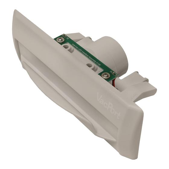
VacPort Model
A910
Without LEDs
Connect the LOW voltage
wire under screw heads.
NOT under Big Washer!
Wall Opening location Pin
Replacing the 'VacPan' or 'Vacu-Sweep' with a VacPort installation
A
C
3
1
3
5
The door is held open by
2 small magnets.
Screw hole to attach VacPort to wall
1) Remove old dustpan from the wall.
2) Use the same 2 screws and attach Trim Plate,
use the holes "A" from the removed VacPan
use the holes "B" from the removed the
VacuSweep
3) Mark the inside of the Trim Plate with a pencil.
4) Remove Trim Plate from the wall and cut the
opening larger along the pencil line.
5) Reattach the Trim Plate to the wall.
6) See page 3 how to attach the 24-volt wires
and Flex-Hose.
7) Now slide the VacPort into the new opening
and secure with the 2 #8 flat head tapping
B
screws and attach to the Trim Plate through
the "C" holes.
By
Installation AND OPERATING MANUAL
MODEL
MODEL
THE VACPORT COMES IN 2 LED LIGHT MODES:
1) WHEN YOU LIFT THE DOOR UP, THE LIGHT IS CONSTANTLY ON, UNTIL YOU CLOSE THE DOOR.
2) WHEN YOU LIFT THE DOOR THE LIGHT STARTS BLINKING, UNTIL DOOR IS CLOSED.
SOME CENTRAL VACUUMS USE A "TRIAC" FOR THE LOW VOLTAGE, OTHER VACUUMS USE A TRANSFORMER TO CREATE
THE 24 VOLT OUTPUT, THE "TRIAC" CREATES THE DISTINCT BLINKING
IF YOU SHOULD HAVE ANY QUESTIONS OR EXPERIENCE A PROBLEM WITH YOUR
DO NOT RETURN THIS PRODUCT TO THE STORE OR DEALER
PLEASE CALL OUR CUSTOMER SERVICE DEPT. AT: 1-888-499-1925
2939 SW 42nd Avenue, Palm City, FL 34990
Phone 772-463-1400 • USA & Canada toll free 888-499-1925
4
www.intervacdesign.com • e-mail: intervac@intervacdesign.com
RECORD THIS INFORMATION
FOR FUTURE REFERENCES
MODEL NUMBER: ________
DATE OF PURCHASE: ______
PLACE OF PURCHASE: ______
Manual #
M-20
Date: 1/2017 Rev.:3/2022
A900
with LED
A910
without LED
PLEASE NOTE:
TECHNICAL EXPLANATION:
INTERVAC PRODUCT,
I
nterVac Design Corp.
Advertisement
Table of Contents

Related Manuals for InterVac VacPort A900

Summary of Contents for InterVac VacPort A900
- Page 1 7) Now slide the VacPort into the new opening and secure with the 2 #8 flat head tapping Phone 772-463-1400 • USA & Canada toll free 888-499-1925 screws and attach to the Trim Plate through www.intervacdesign.com • e-mail: intervac@intervacdesign.com the "C” holes.
- Page 2 Connecting the VacPort to your Central Vacuum top view of VacPort ELECTRICAL REQUIREMENTS: The low voltage Control Wires from your Central Vacuum Cleaner have mostly an 24 Volt output of 24volt AC. Circuit Board Pigtail Wire Note: some Central Vacuums have 24volt DC output. If your vacuum does not start --- just reverse the 2 wires at the wire nuts.
Need help?
Do you have a question about the VacPort A900 and is the answer not in the manual?
Questions and answers