
Related Manuals for Golze Engineering ADL120


Summary of Contents for Golze Engineering ADL120
- Page 1 ADL120 Installation Manual Version 1.02 10.04.2016 ADL120 Installation Manual 1 / 15 Revision 1.02 - 10.04.2016...
-
Page 2: Table Of Contents
External antenna installation ..............8 11.2.3 Antenna testing ..................9 11.2.4 External screen installation ..............9 12 Wiring ADL120 ....................10 12.1.1 25 D-Sub connector- voltage and aviation data ........10 12.1.2 Antenna connector ................11 13 Cooling ......................12 14 Post installation checkout .................. -
Page 3: Version History
Disclaimer The ADL120 is provided as a non certified component. The only basis on witch it can be installed is an appropriate minor change. It is the sole responsibility of the user and installer that is installed and used in a legal way. The device may stop working at any time. -
Page 4: Emergency Procedures
Emergency procedures If you suspect any malfunction of the ADL120 or interference with other aircraft systems, deactivate the device by pulling / deactivating the aircraft circuit breaker for the device or pulling the cigarette lighter plug whichever is applicable. Do not reactivate the device until the problem has been investigated and resolved on the ground. - Page 5 80mm 60mm 53mm 15mm 50mm 15mm 80mm 60mm 53mm 15mm 50mm 15mm Figure 2 - Location of the M4 threads on the front and back side of the ADL120 ADL120 Installation Manual 5 / 15 Revision 1.02 - 10.04.2016...
-
Page 6: Optional External Display
10 Optional external display As optional equipment an external display unit can be connected to the ADL120. The following figures show the dimensions of this screen: 85,0 mm 85,0 mm Figure 1 - Front dimensions of external screen ADL120 Installation Manual 6 / 15 Revision 1.02 - 10.04.2016... - Page 7 10mm Display Bezel 55mm Connector and cable 20mm 10mm Figure 2 - Side view of external screen ADL120 Installation Manual 7 / 15 Revision 1.02 - 10.04.2016...
-
Page 8: Installation
11 Installation 11.1 Inspection Inspect the ADL120 and all supplied parts for condition and completeness. Verify on our website that you have the most up to date version of this installation manual. 11.2 Iridium Antenna The device uses an Iridium antenna to communicate with the Iridium satellite network. -
Page 9: Antenna Testing
Please note that the ADL120 does not provide any lightning protection. When using an external antenna, the antenna must be grounded and provide full certified lightning protection. 11.2.3 Antenna testing Please note that the Iridium network requires a better view to the sky than the GPS receiver. -
Page 10: Wiring Adl120
The device will accept DC 7V to 30V. We recommend installing a 1A circuit breaker in line with the ADL120. For additional protection the device has got an internal fuse rated at 1,6A. The maximum power consumption will be 6W. -
Page 11: Antenna Connector
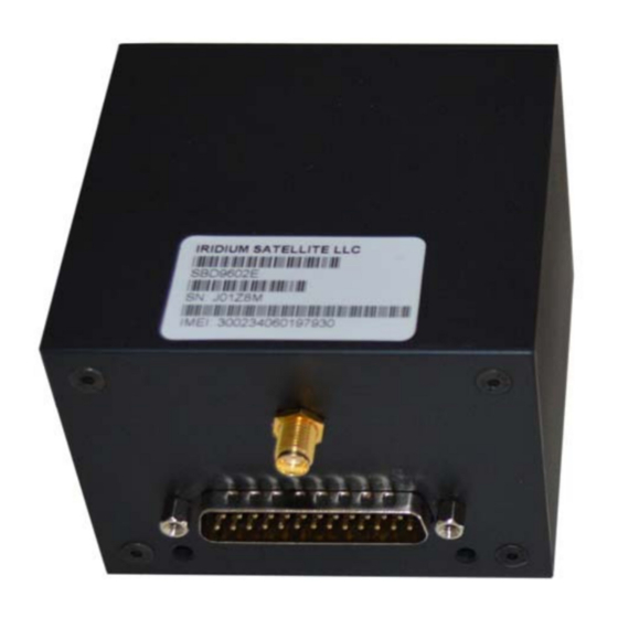
Table 2 - 25pin D-SUB pin description 12.1.2 Antenna connector The device features a rear SMA input. The Iridium SYN7391-C antenna will be delivered with the correct connector. Figure 12 – SMA connector ADL120 Installation Manual 11 / 15 Revision 1.02 - 10.04.2016... -
Page 12: Cooling
13 Cooling Generally the ADL120 does not require any means of active cooling. If mounted in a position where the specified temperature limit might by exceeded, additional air cooling should be implemented. 14 Post installation checkout Disconnect the power connector. Turn on the aircraft electrical system and measure the voltage at the connector is within specification. -
Page 13: Troubleshooting
Verify all connectors and proper power supply. Inspect the device for visible damage. The device does not contain any field serviceable parts. It the device is believed to be defunct please contact us for repair. 19 Specifications ADL120 Voltage: 7 to 30V... -
Page 14: Part Number Reference
20 Part number reference Partnumber Description ADL120 Datalink weather device EXT120 Optional external Touchscreen for the ADL120 ADL120 Installation Manual 14 / 15 Revision 1.02 - 10.04.2016... -
Page 15: Contact
21 Contact Golze Engineering Bredowstr. 29 10551 Berlin http://www.ing-golze.de adl@ing-golze.de +49 30 39805204 ADL120 Installation Manual 15 / 15 Revision 1.02 - 10.04.2016...
Need help?
Do you have a question about the ADL120 and is the answer not in the manual?
Questions and answers