Advertisement
Quick Links
Advertisement

Summary of Contents for Major tech MT190
- Page 1 INSTRUCTION MANUAL MT190 CIRCUIT BREAKER FINDER...
- Page 3 Contents Page no 1. Introduction..................4 2. Features...................4 3. Safety....................4 3.1. International Safety Symbols............4 3.2. Safety Precautions..............4 4. Meter Description................5 5. Specifications...................6 5.1. Electrical Specifications..............6 6. Operation..................7 6.1. Auto Ranging Multimeter............7 6.1.1. AC/DC Voltage Measurements.........7 6.1.2. AC/DC Current Measurements.........7 6.1.3. Resistance Measurements..........7 6.1.4.
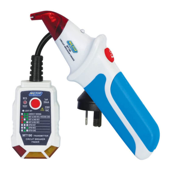
- Page 4 1. INTRODUCTION The MT190 is a Circuit Breaker Finder system that operates on energized circuits, consists of a Transmitter, which plugs into the socket on the circuit you wish to isolate and a Receiver Scanner. The Transmitter sends signals along the cable to the distribution board, the operator simply runs the...
- Page 5 3. METER DESCRIPTION Receiver 1 - Scanning Head 2 - LED indicator , light red during auto scanning. 3 - Signal LED indicator, light green for correct. 4 - Buzzer , Bleeps to indicate auto scanning and Rapid or continuous tone to indicate correct breaker found.
- Page 6 4. OPERATIONS 4.1. Transmitter There is no switch for the transmitter. It will automatically start the injection of the test signal upon connection to a mains supply. 4.2. Receiver The membrane switch on the receiver has 3 functions-On/ReseVOff. Push and immediately release the switch when the receiver is off-this will tum the unit on with a steady beeping and red LED Indicating that the scanning function is in progress.
- Page 7 3. The tester will not indicate the quality of the ground connection, 2 hot wires in a circuit. a combination of defects, or reversal of ground and neutral conductors. 4.5. Receptacle RCD Test 1. Before using the tester. press the TEST Button on the installed RCD receptacle.
- Page 8 (Run the scanning head over the transmitter to check the fuse Finder is operating correctly). • Advice for best performance Due to the differing designs of circuit breakers it may sometimes be unclear from the above procedure which of two breaks the strongest signal comes from, particularly if it appear to come from a boundary area between two adjacent breaker.
- Page 9 2. Rotate the receiver (after resetting) through 90 to set the black pips on the insert of the red scanning head to come towards being in line with the breaker. At some point a stronger signal will be found-scan at the new angle.
- Page 10 (Continue scan slowly across the face of the circuit breakers or fuses) (Sometimes we have noticed some problems. When the receiver is getting closer to correct circuit breaker, the red LED start flashing and there is no LED indication for long time after detecting circuit breaker.
- Page 11 6. Turn the circuit in question off and the receiver will revert to a red LED display and steady beeping. 7. Confirm the correct breaker has been selected by checking that the red LED onthe transmitter is no longer lit. Sometimes we have noticed a problem (mainly occurring on split distribution boards).
- Page 12 MAJOR TECH (PTY) LTD South Africa Australia www.major-tech.com www.majortech.com.au sales@major-tech.com info@majortech.com.au...
Need help?
Do you have a question about the MT190 and is the answer not in the manual?
Questions and answers