
Related Manuals for SEELEY INTERNATIONAL Climate Wizard CW3


Summary of Contents for SEELEY INTERNATIONAL Climate Wizard CW3
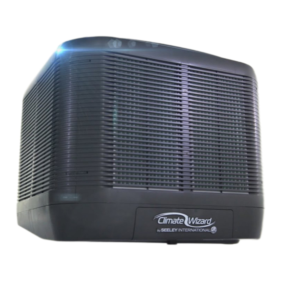
- Page 1 INSTALLATION MANUAL CW3 Microcore Indirect Evaporative Cooler Original English Instructions...
-
Page 3: Table Of Contents
TABLE OF CONTENTS IMPORTANT SAFETY INSTRUCTIONS Read And Save These Instructions For Future Reference. Warning - To Reduce The Risk Of Fire, Electric Shock, Or Injury To Persons, Observe The Following: For Australian Bushfire Prone Areas Employer And Employee Responsibilities Installer And Maintenance Contractors - Risk Assessment Some Points To Consider Other Important Requirements... -
Page 4: Important Safety Instructions
Never force parts to fit because all parts are designed to fit equipment, training and qualifications of workers. together easily without undue force. Seeley International provides the following information as a • Never drill holes in the tank of the cooler. -
Page 5: Cooler Views
COOLER VIEWS 1160mm (45 1/2”) 1160mm (45 1/2”) ILL2677-A ILL2675-A FRONT SIDE 1020mm (40”) ILL2680-A SERVICES UNDERSIDE ILL2679-A (8.0”) (8.3”) CW Logo location Inlet Drain 230 (9.0”) Drain (13.6”) Inlet 570 (22.4”) (suits (20.9”) dropper) 565 (22.2”) (suits 530 (20.9”) dropper) ILL2678-A ILL2676-A Dimensions are in mm (inches in brackets). -
Page 6: Exploded View
EXPLODED VIEW INDEX PART No. DESCRIPTION INDEX PART No. DESCRIPTION 562162 TANK 122342 FAN EXHAUST 562391 CLIP PANEL SIDE 562476 CAP FAN EXHAUST 562438 CLIP PANEL TOP 863832 PLUG VENTURI 562179 PANEL SIDE 863665 STRAPS RETENTION MANIFOLD 855879 FILTER CARTRIDGE 25”x14”x1” 091426 CHLORINATOR LARGE ASSY 562063... - Page 7 EXPLODED VIEW (LEFT HAND ASSEMBLY SHOWN) ILL2982-A INDEX PART No. DESCRIPTION ILL2982-B 14, 15, 122199RP ENCAPSULATION INDIRECT & DIRECT RIGHT 17 & 18 14, 15, 122205RP ENCAPSULATION INDIRECT & DIRECT LEFT 17 & 18 120904P65 CHILLCEL 263*665*35 562124 SPREADER ELBOW CLIP 863208 O RING BS112 CW3 INDIRECT COOLER INSTALLATION MANUAL | 5...
-
Page 8: Cooler Contents
COOLER CONTENTS COOLER INSTALLATION COMPONENTS The cooler will be accompanied by a packout kit box containing control items and other components that are required for installation. ITEM 1 ITEM 2 ITEM 3 ITEM 4 Item Part No. Description ITEM 1. ITEM 2 ITEM 3 ITEM 4... -
Page 9: Installation
INSTALLATION MOVING THE COOLER ASSESSMENT OF ROOF STRUCTURE The cooler can be moved either by fork-truck or pallet-truck THE COOLER REQUIRES AN ADEQUATE ROOF whilst it is resting on its dedicated pallet. Do not drag or lift the STRUCTURE TO BEAR THE LOAD OF ITS OPERATING cooler unless it is on its dedicated pallet. -
Page 10: Cooler Location
5m (17’)) away from any TV antenna or antenna cables. Roofstands, accommodating 0-10 roof pitches, are available for Make sure the cooler is not between the antenna and the order via Seeley International. See Optional Components List. transmission tower that is providing the television signal to the home. -
Page 11: Dropper Details
INSTALLATION DROPPER DETAILS Fit the transition onto the dropper, ensuring that it is orientated correctly, as shown below. Cooler is supported by a 530 x 530mm (20 7/8” x 20 7/8”) dropper with a minimum metal thickness of 1.0mm (20 gauge). The dropper duct must have a raw edge or safe edge at the top. -
Page 12: Mounting The Dropper Assembly
INSTALLATION MOUNTING THE DROPPER ASSEMBLY Lower the dropper into the opening in the orientation shown. Adjust the position of the dropper such that the height tool rests on the high side of the roof. WARNING! The roof must have an adequate load bearing structure. -
Page 13: Flashing The Dropper
INSTALLATION MOUNTING THE DROPPER ASSEMBLY WEATHERSEAL Insert the four (4) T-Washers and push them down into the Reinstall the Weatherseal into the dropper as shown. Ensure transition piece as shown. The T-Washers should be facing they open all the way and do not interfere with the dropper or outwards and will be sitting inside the dropper. -
Page 14: Control Cable Installation
INSTALLATION CONTROL CABLE INSTALLATION Your installation kit includes a control cable. This cable must be routed through this corner recess prior to the cooler being mounted to the dropper. ILL3116-A ILL3029-A Pass the non-taped end of the control cable up into the dropper duct, through the grommet. -
Page 15: Cooler Method Of Installation
INSTALLATION COOLER METHOD OF INSTALLATION LIFTING THE COOLER There are two possible methods of installation for the cooler: Place the slings underneath the cooler and through the dedicated recess channel in the foam supporting blocks. Installation via crane (preferred) – cooler is lifted from its Rocking, lifting and/or blocking up the front of the cooler will be pallet on the ground and slung onto the dropper. - Page 16 INSTALLATION Remove the tape restraining the power cable and allow it to WARNING! BE EXTREMELY CAREFUL NOT TO TRAP dangle loosely. Using the height template tool, guide the mains HANDS IN BETWEEN THE COOLER AND TRANSITION. power cable into the corner recess slot on the transition and DO NOT POSITION ANY PART OF YOUR BODY down into the dropper.
-
Page 17: Installation Cable Connections
INSTALLATION CABLE CONNECTIONS CONTROL CABLE PATH Remove the Control Module cover. Connect the Wall Control communications cable to the free socket labelled “Comms”. The communications cable should be hanging loose on the Connect the Drain Valve cable to the connector/pins labelled outside of the dropper. -
Page 18: Electrical Requirements
Installation of the cooler must conform to local electrical rules, regulations and standards. .Important! It is a requirement of Seeley International that all coolers be connected to a dedicated circuit to the distribution board, with a separate circuit breaker and incorporate a separate isolation switch in accordance with the local wiring rules. -
Page 19: Water Requirements
WATER REQUIREMENTS WATER SUPPLY INSTALLATION WATER HAMMER Climate Wizard requires a permanent water supply to be Not all installation pipeworks are the same, and some may connected. require additional prevention against water hammer. Installation of the water supply to the cooler must conform to If water hammer is a problem, it is the responsibility of the local plumbing rules, regulations, and standards: Installer to fit an appropriate water hammer arresting device... -
Page 20: Installing The Drain Valve
WATER REQUIREMENTS INSTALLING THE DRAIN VALVE Water drained from the cooler must be carried away to a suitable discharge point in accordance with local regulations. Important! Never drain water from the cooler directly on to the roof. The drain valve is not factory fitted to the cooler. This must be completed on site. -
Page 21: Control Schemes
Coolers are supplied with a 20m (66’) control cable. Longer Note! If a BMS is used, it is suggested that technicians obtain cable lengths are available for order via Seeley International. a MagIQtouch Wall Controller as a tool for use during servicing. -
Page 22: Fault Codes Indicated By Led's On The Cooler Electronics Module
FAULT CODES INDICATED BY LED’s ON THE COOLER ELECTRONICS MODULE The CW3 cooler has 2 LED’s visible on the control PCBA. One is Tri-Colour and can glow Green, Red or Amber. The other is Red only. TRI-COLOUR LED Wall Control Fault Description Suggested Remedy Fault Code... -
Page 23: Commissioning Completion Checklist
COMMISSIONING COMPLETION CHECKLIST ROOF REINFORCEMENT □ OWNER INSTRUCTIONS - The owner has been instructed how they can electrically isolate the unit at the meter box in □ GUIDELINES - Have supplied guidelines been followed?. Has case of an emergency. other engineering reinforcement been conducted? DUCTWORK DROPPER INSTALLATION □... -
Page 24: Adjusting Cooler Settings
ADJUSTING COOLER SETTINGS WINTERISATION Within the SETTINGS menu of the MagIQtouch Controller is the Coolers installed in areas where winter temperatures can cause COOLER sub-heading. Here various settings of the cooler can water to freeze should complete the following winterisation be adjusted. -
Page 25: Trouble Shooting
TROUBLE SHOOTING Symptom Cause Action Inadequate Cooling Under-sized ducts. Carry out cooling load design to determine correct size unit, ducting and outlets required. Clogged or dirty cooling cores. Clean or replace cores. Dry cores or lack of water while cooler is operating. Check water distribution system for possible obstruction in hoses. -
Page 26: Appendices
APPENDICES APPENDIX – A GENERIC STRUCTURALLY ENGINEERED ROOF MOUNTING SCHEMES: 24 |... - Page 27 APPENDICES APPENDIX – A GENERIC STRUCTURALLY ENGINEERED ROOF MOUNTING SCHEMES: CW3 INDIRECT COOLER INSTALLATION MANUAL | 25...
- Page 28 APPENDICES APPENDIX – A GENERIC STRUCTURALLY ENGINEERED ROOF MOUNTING SCHEMES: 26 |...
- Page 29 APPENDICES APPENDIX – A GENERIC STRUCTURALLY ENGINEERED ROOF MOUNTING SCHEMES: CW3 INDIRECT COOLER INSTALLATION MANUAL | 27...
- Page 30 APPENDICES APPENDIX – A GENERIC STRUCTURALLY ENGINEERED ROOF MOUNTING SCHEMES: 28 |...
- Page 31 APPENDICES APPENDIX – A GENERIC STRUCTURALLY ENGINEERED ROOF MOUNTING SCHEMES: CW3 INDIRECT COOLER INSTALLATION MANUAL | 29...
- Page 32 APPENDICES APPENDIX – A GENERIC STRUCTURALLY ENGINEERED ROOF MOUNTING SCHEMES: 30 |...
-
Page 33: Appendix - B 'Piece By Piece' Installation
APPENDICES APPENDIX – B ‘PIECE BY PIECE’ INSTALLATION Release the bottom manifold retention straps. The ‘piece by piece’ installation method should be employed as a secondary option when installation by crane is too difficult or not feasible. Important! If using this method, it is imperative that the disassembly and reassembly instructions are followed carefully. - Page 34 APPENDICES APPENDIX – B ‘PIECE BY PIECE’ INSTALLATION Disconnect the cables labelled ‘Top Motor’ and ‘Top Motor Signal’ from the control board ONLY. Removing the Top Motor/Fan Assembly: The cooler electronics enclosure is located between the front and RHS side panels. SUPPLY CHLORINATOR MOTOR (BOTTOM)
- Page 35 APPENDICES APPENDIX – B ‘PIECE BY PIECE’ INSTALLATION Removing the plenum assembly: Reach in to the supply chamber of the cooler and cut the cable If you have successfully freed the top motor cables, you will be tie that is loosely constraining the cables to the inner plenum. able to lift the top motor/fan assembly out from the top of the cooler by lifting it up vertically.
- Page 36 APPENDICES APPENDIX – B ‘PIECE BY PIECE’ INSTALLATION Reposition the vertical hose pillars so that they are resting inside of the tank where they are out of the way. There is an opening at the bottom of the foam plenums which will allow hand access to the clips which are holding the inner plenum to the supply venturi assembly.
- Page 37 APPENDICES APPENDIX – B ‘PIECE BY PIECE’ INSTALLATION Important! Check to make sure that the foam plenums are firmly and correctly fitted to the plenum inner as this forms a sealing face. Important! It is best to leave all other components and assemblies on the ground until they are required in order to Reinstall electronics enclosure in its original position and secure avoid injury and to prevent damage to the components.
- Page 38 APPENDICES APPENDIX – B ‘PIECE BY PIECE’ INSTALLATION Transport all 8 manifold assemblies to the roof and fit to the cooler. To do this, carefully slide the manifolds into the plenum outer ensuring a tight fit with no gaps between the interfacing Route the top motor cables down to the electronics enclosure surfaces.
- Page 39 APPENDICES APPENDIX – B ‘PIECE BY PIECE’ INSTALLATION Once all 4 side panels are fitted, refit all 8 side clips and all 4 top clips. Plumb and connect all hoses to the manifold assemblies as shown. Inner hoses (grey) are to be connected to the upper manifold connection point.
-
Page 40: How To Register Your Product Warranty (Australia Only)
HOW TO REGISTER YOUR PRODUCT WARRANTY (Australia only) Warranty Information section HOW TO REGISTER YOUR PRODUCT WARRANTY (Australia only) Please register your warranty online by visiting seeleyinternational.com and selecting RESIDENTIAL section on the top right hand side of the screen. Then follow these steps: Step 1 Select SUPPORT then REGISTER A PRODUCT FOR WARRANTY Step 2 Enter your product serial number and “SUBMIT”... -
Page 41: Warranty Terms And Information (Australia Only)
Warranty Details (Australia only) In this warranty: We or us means Seeley International Pty Ltd (Seeley) ABN 23 054 687 035, and our contact details are set out at the end of this warranty; You means you, the original end-user purchaser of the Goods;... - Page 42 The warranty granted in clause 1 covers the costs of parts and labour but you will be responsible for: the cost of travel incurred for a Seeley International service agent to get to and from the location of the Goods if the location of the Goods is either: (i) outside the metropolitan areas of the capital cities;...
- Page 43 PRIVACY NOTICE Seeley International Pty Ltd ABN 23 054 687 035 will use the personal information you provide us with to provide warranty support for the product you have purchased and to inform you about other products and services. If you choose not to supply us with the information requested, we may be unable to provide you with warranty support.
- Page 44 6 WITTON ROAD, FOUNDERSVIEW SOUTH, MODDERFONTEIN 1609, GAUTENG, SOUTH AFRICA It is the policy of Seeley International to introduce continuous product improvement. Accordingly, specifications are subject to change without notice. Please consult with your dealer to confirm the specifications of the model selected.
Need help?
Do you have a question about the Climate Wizard CW3 and is the answer not in the manual?
Questions and answers