Table of Contents
Advertisement
Advertisement
Table of Contents

Related Manuals for IECHO BK4 Series

Summary of Contents for IECHO BK4 Series
- Page 2 We are always waiting to serve you. Thank you again for choosing IECHO products, if there is any change for the manual contents due to product improvement, we apologize in advance that we won’t make another notice...
- Page 3 Internal or external changes to the equipment can only be made after prior consultation with Hangzhou IECHO Technology Co., Ltd note The company shall not be liable for safety injuries caused by the use of accessories not authorized by Hangzhou IECHO Technology Co., Ltd...
-
Page 4: Table Of Contents
目 录 1. Equipment Overview ..................................1 1.1. Features....................................1 1.2. Composition ..................................1 1.3. Working Principles ................................1 1.4. Technical Parameters ..............................2 1.5. Cutting head ..................................3 1.6. Cutting tools ..................................4 1.7. Circuit Boards introductions ............................7 2. -
Page 5: Equipment Overview
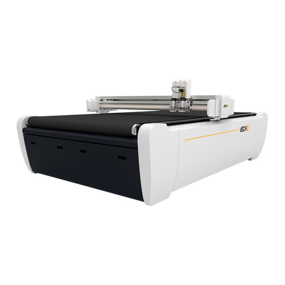
BK4 series cutting machine adopts the overall frame structure layout and brand-new appearance design. Adhering to the design concept of efficient, accurate cutting and intelligent processing of IECHO equipment, it takes a higher level in cutting efficiency, operation stability and noise reduction. -
Page 6: Technical Parameters
Technical Parameters 1.4. Definition Parameter Model BK4-2516 Cutting Area 2500mm×1600mm Machine Dimension 3380mm×2200mm×1330mm According to the configuration, it’s around 10-15 ㎡ Area covered Weight 880KG Max Speed 1800mm/s Max Cutting Thickness 50mm Accuracy 0.1 mm Modules Can be installed up to 2 cutting heads DXF、PLT、PDF、HPG、HPGL、TSK、... -
Page 7: Cutting Head
Cutting head 1.5. Universal All tools can be installed in Cutting thickness: cutting head (Except for milling tools over 450W) 50mm Two punches are set. Punching Max: 10mm Punch head It can punch round holes or thick material slotted and V-shaped knife holes. -
Page 8: Cutting Tools
Cutting tools 1.6. Illustration Name Feature Material Universal Cutting Tool for Cardboard, Chevron board, ABS board, Gasket, Carbon fiber materials up to 5mm thick. prepreg, PVC tarpaulin, PE, XPE, Tangent Fast speed and low cost. Label, e Tool Chevron board, Corrugated High-frequency electric-driven board, Gasket board, Gray tool with 80W power options. - Page 9 Cutting tool with driven Fabrics, carbon fiber, glass rotary blade for fabrics and fiber, aramid, carpet, etc. technical textiles with high Driven processing speed. Rotary Tool...
- Page 10 Illustration Name Feature Material Tool with 5 cutting angles Honeycomb board, (0°,15°,22.5°, 30°, 45°). sandwich board, KT board, Create 3D structural Gray board, etc design V-CUT V-CUT Tool The cutting speed is fast and it is not easy to burn textiles, carbon fiber, glass wire.
-
Page 11: Circuit Boards Introductions
Circuit Boards introductions 1.7. Location diagram of circuit board of electrical box... -
Page 12: Installation
Installation Installation of complete machine 2.1. Loading and unloading 2.1.1. Use a forklift (the arm length of the forklift shall not be less than 2.3m) to operate from the side of the machine, and pay attention to the center of gravity of the machine. Since the center of gravity... -
Page 13: Disassembly And Assembly Of The Cover
of the equipment is biased towards the front end, the cross beam is usually moved to the rear end for fixation. Use lifting device: four lifting ring mounting holes are provided on both sides of the equipment table to facilitate lifting with lifting rings. -
Page 14: Move The Machine
out the packing wooden strip. (forklift or "lengthening" foot can be used to lift the machine) Move the machine 2.1.4. The equipment is equipped with casters, which can be used to move the machine on a flat site. Before pushing the equipment, be sure to "shorten" the anchor to make the casters fall to the ground. -
Page 15: Power Supply
and anchor B to center the bubble of the level. Note that the felt at the place where the level ruler is placed shall be clean and avoid the felt joint. (3) Place the level on the felt at position 2 (x direction) as shown in the figure, and adjust the anchor C to center the bubble of the level. -
Page 16: Air Supply
provide power for computer console, vacuum cleaner, milling cutter, feeding rack, etc. Air supply 2.3. An air source interface is set at the back of the equipment electrical box, and a 12mm diameter air pipe needs to be used to connect the "main air source inlet". Note: if the equipment is equipped with additional functions such as milling cutter and pneumatic vibrating cutter, the corresponding air source interface of the electrical box can be used;... - Page 17 slides into the cylindrical pin on the support plate. Rotate the nose forward with the bottom of the nose as the rotating shaft. Make sure that the stepped cylindrical pin on the support plate slides into the hoist block on the back of the head. ...
- Page 18 Note: the limit slot on the back of the head must fit the clamping step on the support plate. After installation in place, tighten two M5 fixing screws with 4mm Allen wrench.
-
Page 19: Cutting Tools Installation
Cutting tools installation 2.5. UCT installation 2.5.1. Put the sharp knife tool into the machine head, and the red dot in the UCT corresponds to the red dot on the machine head. After the UCT is completely put into the machine head, tighten it clockwise to complete the installation. ... -
Page 20: Eot Installation
EOT installation 2.5.2. Put the EOT into the machine head, and the red dot in the EOT corresponds to the red dot on the machine head After the EOT is completely put into the machine head, tighten it clockwise, lock the fixing block, and the installation is completed. - Page 21 V-CUT installation 2.5.3. First install the blade on the inclined cutter base, be careful about the blade slot and the locating pin on the inclined plane, and tighten two M4 * 8 screws. The red dot is opposite to the red dot. Install the handle part of the oblique knife on the tool base of the machine head.
- Page 22 Place the oblique tool holder at the bottom of the tool handle, and pay attention to the correspondence between the size of the positioning hole and the positioning pin of the tool handle. Lock the inner screw of the tool handle from above with M4 hexagon socket tool.
- Page 23 Creasing tool installation 2.5.4. The red dot is opposite to the red dot. First install the handle part of the oblique knife on the tool base of the machine head. Buckle the pressure shaft into the two rectangular grooves of the tool handle from bottom to top. ...
-
Page 24: Creasing Tool Installation
If it is a breathable material, it needs to be covered with film. Open "IECHO digital cutting system" and import the sample file designed by the user (the data format can be DXF, PLT, PDF, HPG, HPGL, TSK, BRG, XML, cut, oxf, ISO, AI, PS, EPS, etc.). The system... -
Page 25: Electrical Wiring Instructions
Electrical wiring instructions BK4 Circuit diagram of Machine 4.1. -
Page 26: Bk4 Gas Circuit Diagram
BK4 Gas circuit diagram 4.2. -
Page 27: Common Error And Troubleshooting
Common Error and Troubleshooting Item Common error Trouble shooting 1.Check whether the circuit breaker tripped. 2.Check whether the fuse is burned out. Cutter cannot start 3.Check whether the red switch is broken. 4.Check the plug connected to electrical box interface with a multi meter. Check whether the circuit of the 220V power 1.Put one piece of plastic film on the surface of Cutter suction force... -
Page 28: Safety Attentions
Safety Attentions GND electrical wire connected to the ground. Use the required specification wires for electric power connection since the big power of the machine. Check the synchronous belt before switch on the machine, in case it`s blocked by materials fragments. ... - Page 29 This user manual can only be copied with the written authorization of IECHO Science & Technology Co., Ltd. This provision also applies to the excerpts of the manual. IECHO Science & Technology Co., Ltd. reserves the right to interpret the contents described in this user manual.
Need help?
Do you have a question about the BK4 Series and is the answer not in the manual?
Questions and answers
why this error created when we start work on iplycut