
Summary of Contents for Flo Corp UltraFlo UFD3
- Page 1 ’ User Manual UltraFlo™ UFD3 ULTRASONIC CLAMP-ON FLOW METER Ultrasonic Flow Meter User Manual Small Pipe Solution...
- Page 2 Preface Thanks for purchasing the product! The User’s Manual covers functions, settings, wiring and troubleshooting methods of this flowmeter. Please carefully read this manual before use. After reading the manual, please keep it in a proper place for reference when you operate the flowmeter.
-
Page 3: Table Of Contents
Contents Product Liabilities and Quality Assurance ............5 Descriptions of the Flow Meter ............... 6 Chapter II Descriptions of the Flow Meter ..............6 Delivery Scope....................6 Measuring Principle ..................7 Application Scope ................... 7 Chapter III Electrical Connections ................. 8 Safety Prompts .................... - Page 4 Copyrights and Data Protection Content of this file has been carefully checked. We don’t promise that the content is totally correct and completely identical with the latest version. Content of this file and related products are under protection of USA copyright laws. Without authorization in writing of the Company, please DO NOT try to reproduce, transfer, transcribe or translate any parts of the flow meter including the source code to any languages or computer language in any forms or through electronic, electromagnetic, optical or...
-
Page 5: Product Liabilities And Quality Assurance
1.1 Product Liabilities and Quality Assurance The purchaser should judge by himself whether the flowmeter is applicable or not, and shall bear related responsibilities. The manufacturer would bear no responsibilities for any consequences arising from the purchaser’s misuse of the flowmeter. The purchaser may lose the rights for quality assurance if the flowmeter or the system is installed or operated in a wrong way. -
Page 6: Descriptions Of The Flow Meter
1.2 Descriptions of the Flow Meter Caution! For your safety, please carefully read the following safety instructions before use. With this manual, you could set up correct operating conditions of this flowmeter to ensure safety and efficiency in use. Only certified personnel who have received related training are allowed to install, use, operate and maintain this flowmeter. -
Page 7: Measuring Principle
2.2 Measuring Principle This series of ultrasonic flowmeter is an industrial time-difference type ultrasonic flowmeter. It applies the latest industrial-level PFGA, which extremely improves the signal sampling frequency and bubble tolerance rate; the self-developed TGA technology makes it be capable of dealing with more complex logic and calculation to provide more accurate and faster measurements, and ensures the flowmeter could endure non-continuous bubbles or impurities within 5 sec. -
Page 8: Chapter Iii Electrical Connections
Chapter III Electrical Connections 3.1 Safety Prompts Warning! DO cut off the power before any electrical connections. Please pay attention to the power supply data on the nameplate. Caution! Please strictly comply with local professional health and safety regulations. Only trained personnel are allowed to operate the electrical equipment. -
Page 9: Connecting Electrical Cables
Internal shield should be connected through the multi-stranded drain wire. It is recommended to use "RVVP" shield cables as electrical connection cables. The power cord should be connected from the hole on one side and the signal cable should come out from the hole on the other side. -
Page 10: Transmitter Connections
3.4 Transmitter Connections 3.4.1. Power supply Please pay attention to the power supply. Please connect related power supply according to the symbols of connecting terminals. 3.4.2. Transmitter connections Once the flowmeter is installed at the designated place as required, you can start connections. Please connect the cable according to the wiring mark, the specific explanation is as follows: Power supply DC10-24V + Power supply DC10-24V -... -
Page 11: Chapter Iv Operation Panel And Quick Start
Chapter IV Operation Panel and Quick Start 4.1 Power on Warning! Please check the meter is correctly installed or not before power on, including: Connecting the power supply as specified; Please check the electrical connection of the supply power is correct or not. 4.2 Keyboard Operation Descriptions 4.3.2... -
Page 12: Quick Start
4.3 Quick Start Basic settings We will take PVC pipe for example. Related parameters: Outer diameter 20mm, wall thickness 4mm, and material is PVC with no lining and the medium is room temperature water. Step1.Pipe Size setting M10 Pipe settings Input the outer diameter and wall thickness. - Page 13 Step 3. Measurement liquid setting M12 Medium Select liquid you measure on site and following liquid types are available in the menu: 0. Water 1. Other ((If you choose others, please input the liquid velocity) Step 4. Transducer type M13 Transducer No need to set here Step 5.
-
Page 14: Pipe Design And Selection
5.2 Pipe Design and Selection The following should be taken into account when selecting a pipe: 5.2.1 Installation Environment It’s better to install the flowmeter indoors; if you have to install it outdoors, you should take measures to avoid direct sunlight or rainwater. The flowmeter shall be installed away from high temperature, thermal radiation from equipment or corrosive gas. - Page 15 Caution! DO ensure that the flowmeter is filled. DO NOT make the liquid flow downwards vertically, or it may have bubbles. Caution! To ensure measurement accuracy of the flowmeter, try to satisfy the following requirements on the length of straight pipe sections installed nearby the flowmeter: upstream >20D, downstream>10D.
-
Page 16: Transducer Installation
Install after valves Install on diameter-reduced pipe Install on diameter-expanded pipe 5.3 Transducer Installation 5.3.1 Transducer Installation Steps 1. Please set parameters of M10 and M12 according to the actual situation on site, and adjust the end distance of the sensor according to the installation distance of M14. As shown in the figure below. - Page 17 2. Fix the flow meter bottom part on the pipe on with the rubber strap supplied with the product. 3. Insert the four fixing brackets of flow meter top part into the corresponding holes.
- Page 18 4. Lock screws to fix both top and bottom part of flow meter. 5. Insert the aviation plug of the upper cover into the corresponding position of the bottom cover and tighten it. Then the installation is complete.
- Page 19 5.3.2 Confirmation on Installation Quality Enter M04 menu Status Status Signal Signal Sound Time Sound Time Status Sound Signal Time Signal strength (UP/DN indicates upstream/downstream transducer): Ultrasonic Flow Meter applies 00.0-99.0 to indicate corresponding signal strength, the bigger the value, the stronger the signal strength. In normal operation, the signal strength of the upstream/downstream transducer should be >85 as required.
- Page 20 Sound velocity: Vel. value indicates the sound velocity and the actual sound velocity measured by the flowmeter. Under normal conditions, it should be close to the sound velocity shown in M12 menu. If the difference is too big, you should check the installation settings and whether it is properly installed or not.
-
Page 21: Chapter Vi Operation
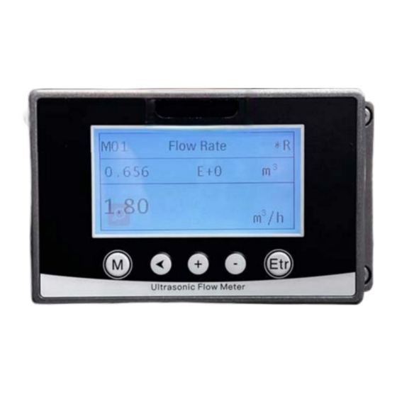
Chapter VI Operation Note: The flowmeter would be calibrated and debugged before leaving factory, and its parameters would be set accurately. Please carefully read the instructions if necessary. Non-professionals are not allowed to operate the flowmeter. 6.1 Common Functions 6.1.1 How to Judge its Operating Status If it displays "*R", it indicates the flowmeter works normally. - Page 22 need to set zero point to improve the accuracy for small flow measurement. At the time, you need to cut zero point on site. Cut zero steps: M22 menu-Cut-1. Yes, it displays “success” if zero point is cut. and the flowmeter would return to M01 menu.
- Page 23 the flow direction, you could set 1000 and 2000 as the minimum and maximum limit values respectively in M32 menu. However, when 0-4-20mA output is used while considering the flow direction, you should consider two different conditions; when the flow direction is reverse, the output current is 0~4mA;...
- Page 24 6.1.8 Alarms (Option output) Switch output alarm signal is generated through switching on/off OCTs or relays and output to the external circuit, it is generated under the following conditions: Transducers can’t receive ultrasound signals; Ultrasound signals that transducers received are too poor; The flowmeter is not under normal operation;...
-
Page 25: Description Of Operation Menus
6.2 Description of Operation Menus 6.2.1 Abbreviated codes of menus Level One Menu Menu Codes and Description Details Net total M00 Flow Total Positive total Negative total Flow Rate Flow rate & Flow velocity Measurement value & status Heat total & temperature M02 Heat (Optional function) difference (ΔT) *R- System Normal... - Page 26 M23 Totalizer Totalizer type setting & Reset M24 Temperature sensitive Effective temperature difference M26 K factor setting Multi points calibration (Calibration M27 Calibration flow velocity value is fixed) M28 4-20mA setting M29 RTD adjustment Temperature off set M30 RS 485 Baud rate &...
- Page 27 Multiplication factor M43 Temperature ℉ & ℃ M50 SN & Software version M53 Language setting Chinese/ English M54 System lock & Password word M55 Reset & Interface Settings System setting 6.2.2 Menu operation Settings In the Primary menu state, press M to switch between the six categories of menus M key M key Setting...
- Page 28 The following uses media type as an example: Primary Menu “ <” “Etr” Secondary Menu “Etr” “ +” “-” Previous option M12 Enter the Next option state setting (Medium type) (Medium type) “Etr” Save the current option and return to the secondary menu Number entering operation instructions, Take the setting of a low flow rate cut off value as an example M21 Primary Menu...
- Page 29 6.2.3 Menu Operation Description Flow Total Pipe setting “+” Flow Rate Medium setting Heat Transducers M02 and M03 is Cool the option function, only Install space display when the instrument is an energy Status (Btu) meter. Status M20 Damping M29 RTD M21 Low flow cut off M28 4-20mA setting M22 Zero-point setting...
- Page 30 M40 System M30 RS485 unit M32 4-20mA M41 Flow unit M42 Energy Frequency unit Relay/Alarm Temperature unit M50 Serial info M53 Language M54 System lock M55 Reset...
-
Page 31: Chapter Vii Common Faults And Troubleshooting
Chapter VII Common Faults and Troubleshooting Note: Each flowmeter would be strictly tested and checked before leaving factory. However, it would still fail to work because of incorrect operation, wrong settings or bad working conditions. The following shows the common faults happened in operation, and provides analysis and related solutions. -
Page 32: Chapter Viii Communication Interface And Communication Protocol
Chapter VIII Communication Interface and Communication Protocol 8.1 General The flowmeter is provided with an UART protocol, and you also could operate by using RS- 485 Modbus. There are two basic structures you could choose for networking, i.e. only applying the analog current output method or directly applying the UART communication method of the flowmeter. - Page 33 8.3 Communication Protocol and its Use The flowmeter supports HL protocol and MODBUS protocol. 8.3.1. HL protocol The flowmeter applies HL communication protocol. The host device would request the flowmeter to respond after sending a “command”. Asynchronous communication baud rate (Main station: computer system;...
- Page 34 sum data returned =2BH + 31H + 32H+ 33H + 34H + 35H+ 36H + 37H+45H + 2BH + 30H + 6DH + 33H + 20H = 2F7, and the least 8-bit binary is F7. Therefore, data of command PRT(cr)(lf) is + 1234567E + 0m3!F7(cr)(lf), "!" as for delimiter, the first part is the character for summation and the second part is an 1-bit check code.
- Page 35 MODBUS protocol function code 0x06 Information frame format of the write-in single register sent by the host (function code 0x06): Operation Register’s first Number of Slave address Check code function code address registers 1 byte 1 byte 2 bytes 2 bytes 2 bytes 0x01~0xF7 0x06...
- Page 36 Write-in commands are shown below: 0x01 0x06 0x10 0x03 0x00 0x02 0xFC 0xCB Flowmeter’s address function code/Register address/Number of registers/ CRC check code Flowmeter’s feedback data: 0x01 0x06 0x10 0x03 0x00 0x02 0xFC 0xCB Flowmeter’s address function code/Register address/Number of registers/CRC check code Error processing The flowmeter only returns the error code 0x02, it indicates that the first address of data is wrong.
- Page 37 32 bits real $000E 40015 NET Total-low word $000F 40016 NET Total –high word $0010 40017 NET Total –exponent 16 bits int. $0011 40018 Energy flow –low word 32 bits real $0012 40019 Energy flow – high word $0013 40020 Energy total(hot) –low word 32 bits real $0014...
- Page 38 Address list of single write register (Writing with 0x06 function codes) Data Register Data Read/Write add. Type Registers $1003 44100 Flowemeter add. (1-255) 16 bits Communication Baud Rate 0 = $1004 44101 16 bits 2400,1 = 4800, 2 = 9600, 3 = 19200, 4 = 38400,5 = 56000 1.
-
Page 39: Appendix. Related Measurement Database
Appendix. Related Measurement Database Acoustic velocity of common pipes Acoustic Velocity Acoustic Velocity Pipe Material (m/s) Liner Material (m/s) Steel 3206 Teflon 1225 2286 Titanium 3150 Aluminium 3048 Cement 4190 Brass 2270 Asphalt 2540 Cast iron 2460 Enamel 2540 Bronze 2270 Glass 5970...
Need help?
Do you have a question about the UltraFlo UFD3 and is the answer not in the manual?
Questions and answers