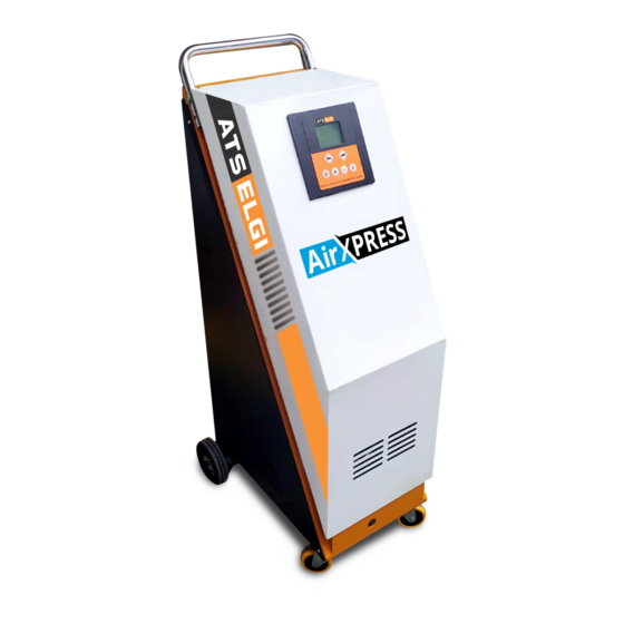
Summary of Contents for ATS ELGI AIR XPRESS
- Page 1 TYREINFLATOR (BuiltinCompressor) NEW GEN BIC TYPE INFLATOR MODEL: AIR XPRESS TPLNO: S15024 Operation,Maintenance&PartsManual...
- Page 2 © ATSElgiLimited Coimbatore,TN-641021,India PrintingStatus R01Dec2021 ContactInfo:ATS ElgiLimited Kurichy,Coimbatore,TN-641021 Phone 91-422-2589999 91-422-2589800 e-mail enquiry@ats-elgi.com TollFreeNo. 1800-203-3544...
-
Page 3: Table Of Contents
CONTENTS PageNo. Introduction TechnicalData Scopeofsupply Installation DescriptionofControllerUnit OperatingInstruction MaintenanceSchedule TroubleShooting PartsList 9.1. Parts list old model 10. ElectricalWiringDiagram 11. Electrical line Diagram 12. Do’s&Don’ts ATSElgiWarrantyPolicy... -
Page 4: Introduction
1. INTRODUCTION PrincipleofOperation: controllerdisplaypanel.A detailedlistofvehiclesandresp Thisproduct,Tyreinflatorisele ectiverequiredpressureare ctronicpre-settypewith availableinthelaterpartofthisman microprocessordrivencontroller ual. unit. Apiezoelectrictransducer,calledh Operation: ereaspressuresensor,isemplo Whentherequiredpressureissetint yedtoconverttheinputenergyf r hecontrollerandthefootvalveispre omthef ormofcompressedairt ssedoverthetyrevalveinavehicle oelectricalsignaloutput.Theel orotherwise,theair ectricalsignalsthusderiv edar underpressureflowfromthetyrean dreachesthecontrolthroughthep modulated,manipulatedandpr ressuresensor.The ocessedinthecontrollerunitwitht pressureinsidethetyreisconv hehelpofmicroprocessors.Thisint ertedbythepressuresensortoele urnprovidestheoperator ctricsignalsisthenregisteredint themeans ofoperating hecontroller. unitwithdisplaysandcompressed Themicroprocessoristhenind air routingtodesiredports. - Page 5 4. General Trainingneeds Atthisjuncture,wewishtothank Regardingtrainingeitheronthispr youforpurchasingthisqualitypr oductoranyotherproductsofELG oduct.Thismodernpneumaticm I,pleaserefertosectiontitled"Tr achinehasbeendesignedtopro ainingCentre videyouwith Information"givenlaterinthisma manyhoursofusefulservice. nual. ProductReferences, ThisOperationandMaintenance llustrationsandSpe Manualprovidesyouwi t heasy cifications -to- understandoperatinginstructio Allinformations,illustrationsands ns.Readtheentiremanualandf pecificationsinthismanualare ollowalltheinstructionstokeepy basedonthelatestproductinfor ournew mationavailableatthetimeofprinti pneumaticmachineintopoper ng.Wereservetherighttomakech atingcondition. angesatanytimewithoutnotice. 06. ServiceInformation Thismanualcomprisesofapart sli sti na d d i t i o nt oarecomm e Serviceonthispneumaticmac ndedsp aresl i st ,providingyoui hinewithinandafterthe...
-
Page 6: Technicaldata
6. Requiredquantity 1. Model Duetoimprovementsbeingmadec 2. FabricationNo. onstantlyandcontinuously,theill ustrationsanddescriptionsonthi 3. Yearofmanufacture smanualarenotbinding 4. Partname 2. TECHNICAL DATA Description Unit Data Model —- AIR XPRESS OperatingPressure 0-170 PressureSettingRange 7-170 OverLoadPressure +10%-15% InputPowerSupply TotalPowerConsumption ControllerDetails —- —- Display —- —- 1.Type —-... - Page 7 Description Unit Data Accuracy ±0.5%offullscale LengthofOutletAirHose LengthofPowercard CompressorDetails —- —- Model —- VayuRAC2Hp OperatingPressure Kgf/cm Displacement Motor —- —- 1.Type —- SinglePhasePermanent SplitCapacitor(PSC) 2.Rating +10%-15% 3.Voltage ElectricalProtection —- 20A, 2P MCB Mounting —- TankMounted TankCapacity Litre OverallDimensionLXWXH 335 X 503 X 1037 ± 10mm Weight —- 95kg Approx...
-
Page 8: Scopeofsupply
3. SCOPEOFSUPPLY BuiltinCompressorcomprisingof Cabinetcontainingmainelementsviz.compressorwithtank,SMPS Board,ControllerPCB,MCB,solenoidvalves,pressersensor,Buzzeret StandardAccessories SpiralhoseAssembly10Mwithclip connector, 3corecableof1.5mlong 4. INSTALLATION Don’tunpacktheequipmentunlessthesiteisreadyforinstallation. Theunitneedselectricalconnectionwith230volt(+10%-15%)AC Singlephaseforfunctioning.Thepowercordwithofsuitablespecificat ionissuppliedwiththisunit. Check/Filltheoilinthecompressorcrankcaseareasrecommended. Take outthe(PU tube)autodrain valveoutletto theoutsideofthecabinet. Connecttheelectricalcablewiththemainpowersupply. Ensureproperearthingisgiven. Note Donotoverloadcompressorforalongperiodeventhoughitis ofcontinuousrating,aswerecommendintermittentuseonly. RECOMMENDEDOIL ELGIAIRLUBE 200ML... -
Page 9: Descriptionofcontrollerunit
5. DESCRIPTIONOFCONTROLLERUNIT 5.1 DescriptionofLED: OPERATING INSTRUCTION Powering on the unit, the display will switch on as below:... - Page 10 1. Unit select Device has four units that can be chosen by the user. kpa – psi – bar - kgf Unit set here will become default unit for following usage, do not need to set unit each time. Press【i】,【SET】 will be shown on the LCD screen, and the unit will be flashing.
- Page 11 OPERATING INSTRUCTION 4. Inflation and Deflation Press【P1】or【P2】to choose a target pressure value Press 【+】or【-】to select target pressure. Connect with tyre, ensure no air leaks, inflator will work automatically. When inflation is finished, machine will stop automatically and BEEP to remind users. Disconnect the air hose from tyre, finish inflation.
- Page 12 Control panel functional key details Reduce final target pressure Increase final target pressure Function Select: Unit Change/OPS set Function Select Confirm/Start to inflate/Stop. Used this button to start the inflation process when the pressure in the tyre is less than: 3 Psi, 20 Kpa or 0.2 Bar.
- Page 13 6. OPERATINGINSTRUCTION 6.1COMPRESSORUNIT:a).S TARTING: Checkthemainpower,shouldbematchedwiththerequiredpower. Switchonthemainpowersupply.MCB(20A). Turnthepressureswitchknobfittedonthetankintoposition“1”. Thecompressoriscontrolledbythepressureswitchwhichstopsitwhent ankpressurereachesmaximumvalue(170psi)andrestartsitwhenitfall stomaximumvalue(110psi). Loadittomaximumpressureandcheckexactlyhowthemachineisope rating. Note Themotorofthiscompressorisequippedwithanautomatictherm albreakerlocatedinsidethewinding– thisstopsthecompressorwhenmotortemperaturereachesexces sivelyhighvalues.Ifthebreakeristripped,thecompressor.Restarta utomaticallyafter10to15minutes. 6.2.CONTROLLERUNIT a)INFLATING/ DEFLATING TYPE: Switchontheselectorswitch Pre-Setthedesiredpressurebyusing+ / -keys Connectthefootconnectortothetyre(unitwillinflate/deflateauto matically) Waitforthebeepsignal Removetheconnectionfromthetyre UseTyrekeyforempty[Airlessthan7psipressure]tyreonly.
-
Page 14: Maintenanceschedule
7. MAINTENANCESCHEDULE a). Compressor Beforeattemptinganymaintenancejobsonthecompressor,makesure ofthefollowing. Mainswitchcontrollerunitswitchandpressureswitch-allarein ‘off’position. Nopressureintheairtank. Every50hoursofworking:dismantlethesuctionfilterandcleanthefilterin gelementbyblowingcompressoraironit. Thecondensatewaterintankmustbedesiredeverydaybyopeni ngthedrainvalveunderthetank. Oilchange First100hoursofworking,afullchangeofoilisrecommended. Unscrewtheoildrainplugonthehousingcover,allowalltheoiltofl owoutandre screwtheplug. Pouroilintotheupperholeofthehousingcoveruntilitreachesthe levelindicatedonthestick. Checktheoillevelinthecrankcaseonceinaweekandtoppingupitifnece ssary. b).TyreInflator Checkthe rubberwasherinthefootconnectorat leastonceinaweek. Checktheelectricalwiringat leastonceinamonth CleantheSolenoidvalvestembycompressorair. -
Page 15: Troubleshooting
8. TROUBLESHOOTING PROBLEM POSSIBLE CAUSE SOLUTION Air leak Leak in the connection Check the pneumatic Connection The inflator works, Obstruction in filters or Clean the filters and But no air inflated in air system check the air tube No display Check power supply Reconnect Inflation does not... - Page 16 Problem Possible causes Solution Atmaximumpressureintank, a p p l y soapwatersolution ontoallconnectionsandjoints. Leakage through joints, Pressuredropintank connections Lookforbubblesandtighten Connectionsorjointswhere leakageisvisible Poorelectricalconnection Checkelectricalconnection. Thecompressor Motortripswitchhascutin Clean&tightenasnecessary stopsanddoesnot startagain ContactATSELGIService Motorwindingsburnt Technician ContactATSELGIService Motor bearings failure Technician Seizure piston ContactATSELGIService Cylinder becauseof Motorshafttightand Technician doesnotrotate...
- Page 17 Exploded view / part list...
- Page 18 9. PARTLIST...
-
Page 19: Partslist
9.1.PARTLIST – OLD MODEL Fig3 PARTSLISTFORTYREINFLATORBUILTIN COMPRESSOR... - Page 20 Sl.No DESCRIPTION QTY. ITEMCODE CABINET 150330960 COMPRESSORVAYURAC2HP 340303930 TANKCOMPRESSOR 150330710 CONTROLLERWITHOUTSMPS 150402410 VIBRATIONMOUNT 150481260 ACPIPEASSY 150330720 FUSE,2A 008927011 MCB,20A 008927022 RETRAIDENTFIBRE 000999821 HOSEASSYNYLON7mWITH S.E.F.CONNECTOR 150400180 BUZZER 150402030 PRESSURETRANSMITTER 150400260 SOLENOIDVALVE2/2NC 150402300 SMPSBOARD 150302240 FRC1/4"BSP 150402150 PU8HOSE 200450130 BOLT,HEX,M6X20 000906086 NUT, HEX, M6 000948007 *Notshowninthefig...
- Page 21 Compressor part codes...
- Page 22 Sl.No DESCRIPTION QTY. DRAWING DRAWING VAYU2HP X340065 X340070 CYLINDERHEADASSY 340302440 340303870 GASKETVFTOHEAD 340401830 340401830 REEDVALVEASSY 340302260 34030226A GASKETVFTOCYLINDER 340401820 340401820 CYLINDER 340302410 340303850 RINGTPC 00041589A 00041589A RINGSC 00041590A 00041590A RINGSOC 00041683A 00041683A PISTONANDGPIN 340400920 34040091A CONNECTINGROD 340301650 340303920 GASKETCYLINDERTOCC 340403130 340403130 DIPSTICKASSY 34040010A...
- Page 23 Air tank assy Sl.No DESCRIPTION QTY. ITEMCODE TANK,COMPRESSOR30LBIC 150330710 NIPPLE1/4"X1/4" 020514840 SAFETYVALVEVAYURACUNIT A340012 340403440 MALEELBOW¼”BSP 200450110 PRESSURESWITCHVAYURACUNIT B185108 PLUG1/4"BSP 150480370 CHECKVALVEVAYURACUNIT NRVA340010 340403200 PLUG1/2"BSP 110510330 VALVEASSY,DRAIN 020515411 AIRHOSEPU6.075M 120430571 ACPIPEASSY 150330720...
-
Page 24: Electricalwiringdiagram
10. ELECTRICALWIRINGDIAGRAM a).Compressor A =POWERSUPPLY P =PRESSURESWITCH =AUTOMATICTHERMALPROTECTIO NSW ITCH TM=MANUALMPEROMETRICPROTECTIO NSW ITCH 1.2.3.4-5- 6=WIRECONNECTIONTER MINALS C =CONDENSER M =MOTOR AU=AUXILIARYWINDING AM = STARTINGWINDING... -
Page 25: Electrical Line Diagram
b)Controller ELECTRICAL LINE DIAGRAM... -
Page 26: Do's&Don'ts
12. DO’S&DON’TS DO'S 1. COMPRESSOR Keeptheairfilterclean (Airfiltercanrestrictthemoisturefromenteringandpassingthrou ghtheunittoaspecifiedlevelonly.Henceensuringmoisturefree airfromthecompressedairsourceitselfishealthyfortheproduct. Draincompressorairreceiverdaily (2&3.Dirtandmoisturecontaminantstheairwilldamageandreduc ethelifeofsolenoidvalvesandotherrelatedelements Callnearbydealerforairpressurecalibrationfocontr ollerperiodically (Calibrationwillensurecorrectpressureofairmediumworking intheunitwhileacycleofdeflatingorinflatingisinprocess Keepcontrollerdoorclosedwhennotinoperation (Topreventdustfromenteringtheboxwhiletheunitisnotisoperati Callnearbydealer/branchifcontrollermalfunctions(Se rvicingofthecontrollerhastobeentrustedtoauthorized personnelofELGIonly) Regularlycheckforleaksintheairhoses (Leakagewillleadtoincorrectfeedbackmechanismofair pressureatdifferentstagesofadeflatingorinflatingcycle) Checkifautodrainisworkingperiodically... - Page 27 DON’TS □ DoanyrepairworkwhiletheunitisONcondition (Thisistoensuresafetyfortheunitandthepersonnelworking withtheproduct) □ OpentheControllerforservice (Controlleristheheartoftheunitandservicingthesamewitho utadequateknowledgeisnotrecommended) □ Meddlewiththewiringinsidethemainbox (Wrongconnectionwillleadtoelectricalfailureoftheproduct) □ Usecompressorairinparallelwithanyotherequipment(Toens uresafetyandlonglifeoftheproductitisessential thatanyotherequipmentisnotruninparallelwhilethisprod uctisinoperation)
-
Page 28: Atselgiwarrantypolicy
ATSELGIWARRANTYPOLICY Thiswarrantypolicyisapplicabletotheequipmentsuppliedby ATSElgiLimited.(hereinaftercalledthecompany) Thescopeofthewarrantyexcludesnormalwear&tearofparts, rubbercomponents,electricalitems,consumables(oiletc),gauge, wheels,filter,battery,glassitems,lock,cable,keypad,printer ribbon,PrintedCircuitBoard,cartridge,probeetc.fromthepurview ofourstandardwarranty. Ifanydefectshouldbefoundinthesuppliedequipmentwithin thetermofwarrantystipulatedabove,thecompany’sonly obligationistorepairorreplace,atitssolediscretion,anypart showntobedefectivewithanewpartorequivalent,freeofcost, whenthecompanyacknowledgesthatsuchadefectisattributable tofaultymaterialorworkmanshipatthetimeofmanufacture. Thecompanyisresponsibleonlytillthepointoffirstsaletothe ultimatecustomerandnotthereafterandwarrantyisavailable onlyifthepurchasesareeitherfromthecompanyoritsauthorized dealers;Thecompanydisownsliabilityonthepurchaseofany secondhandmachineorpurchaseotherwisethanfromauthorized dealers. Theliabilityofthecompanyislimitedtotheproductsoldandthe companyshallnotbeliableforanyindirect,incidental,punitive, specialorconsequentialdamagesarisingoutoforinanyway connectedwiththeusageoftheproductsorinformationinthe saidmanual. Thewarrantyshallnotapply: foranydefectsornon-compatibilitythatthebuyershould haveknownatthetimeofpurchaseoftheequipmentie., thecompanyisnotresponsibleiftheequipmentisused forpurposeotherthanithasbeendesignedfor. - Page 29 anydefectcausedbymisuse,negligence,abnormaluseor insufficientcare. iftheequipmentismodifiedoraltered. iftheequipmentisnotinstalledornotmaintainedasprescribed. iftheequipmentisnotoperatedinaccordancewithoperator/ servicemanual. ifdefectscausedbyelectricalfluctuation,vibration,soundor anyotherexternalfactorlikepollutionetc. ifassembled,disassembled,adjusted,mishandledorrepaired byanypersonotherthanATSElgiEngineerorATSElgiauthorized technician. forcertainspecializedproductsoperatingthesamewithout receivingpropertrainingasstipulatedforbyATSElgi. Theaforesaidinstancesareillustrativeandnotexhaustiveandthe companyreservesitsrighttoaddadditionaltermsasandwhen desired. Thebuyershouldtakecareofthefollowingwhenreturningan equipmentallegingdefectwithintheperiodofwarranty acopyoftheinvoiceshallaccompanytheequipmentforwhich warrantyisclaimed itispackedintheoriginalpackingwithwhichitwassoldtothe saidbuyer. Abriefdescriptionofthedefect/problem. Thecost(inclusiveofinsurance,ifany)oftransportationof goodstorectifysuchdefectsshallbebornebythebuyeronly. ATSElgireservesitsrightstoaccept/rejectanydefect/return. Anydisputepertainingtothesaidmanualoranythingstatedtherein oranyproductstatedthereinissubjecttotheexclusivejurisdictionof thecourtsinCoimbatore.
- Page 30 Notes...
- Page 31 Notes...

Need help?
Do you have a question about the AIR XPRESS and is the answer not in the manual?
Questions and answers