
Summary of Contents for AIRfire ARMANfire FK-5-1-12
- Page 1 PRE-ENGINEERED SUPPRESSION SYSTEM Installation and Maintenance User Manual Automatic fire suppression system for small enclosure applications (LPCB Certified up to 2m FK-5-1-12...
- Page 2 Technical Users Manual ARMANfire Cabinets FK-5-1-12 – TUMARFCABFK5EN – V1.1 – Date: 29/04/2020 Page 1 of 46...
-
Page 3: Table Of Contents
INTRODUCTION GENERAL HAZARD NOTICE FUNCTION OF THE EXTINGUISHING SYSTEM DIRECTIVES FOR USERS OF THE SYSTEM 1.4.1 INSTALLERS AND SERVICE PERSONNEL 1.4.2 FIRE SAFETY OPERATORS SYSTEM DESIGN GENERAL SYSTEM DATA APPLICATION LIMITS SYSTEM COMPONENTS Extinguisher container – Cylinder (code: 03420X) Cylinder valve (code: 0742A0) Easydetect sensor tube (code: 125101) Easydetect tube fittings Cylinder brackets... - Page 4 Reinstatement work after system discharge 8.1.1 Replacement of single use components 8.1.2 Replenishing discharged extinguishing agent Servicing after an interval 8.2.1 Service intervals 8.2.2 Maintenance schedule 8.2.3 Yearly check – System functionality check 8.2.4 Biannual check – Checking operational state of components 8.2.5 10year check –...
- Page 5 A.Esteruelas IMPORTANT The information contained in this manual is property of AIRfire Worldwide, who reserve the right to carry out changes without prior notice. No reproduction, modification, total or partial translation is allowed for any purpose than internal use. Every effort has been made to ensure accuracy of information contained herein, however, AIRfire disclaims any liability for the use that may be made of this information.
-
Page 6: Introduction
Limits and values listed in these operating instructions shall be observed, particularly operating pressures, ambient temperatures and dimensions of the system installation too. The company AIRfire will accept no liability for damages resulting from improper use or non-compliance with the instructions in this user manual. -
Page 7: Function Of The Extinguishing System
Intention of this manual is to give specific instructions for installation, maintenance, and testing requirements for AIRfire systems and components. In any case is intended to accomplish any requirements of the applicable and mandatory standards of design and installation of systems. -
Page 8: Fire Safety Operators
In addition, the operating instructions to the individual components complementing the information in this documentation must be observed. Do not hesitate to contact AIRfire in case of overlapping, missing information or doubts. 1.4.2 FIRE SAFETY OPERATORS The system components shall never be damaged, disassembled or readjusted during operation of cleaning/ maintenance work. -
Page 9: Figure 1 - Ball Valve Position
Lever shut – System out of Lever open – System operational Valve opened Valve closed Figure 1 - Ball valve position Never sever the sensor tube as this would trigger the extinguishing process. The ball valve of the extinguishing system must never be shut by non-authorised staff as this would prevent any extinguishing action. -
Page 10: System Design
SYSTEM DESIGN 2.1 GENERAL SYSTEM DATA Extinguishing agent used FK-5-1-12 (ISO name) Nomenclature 1,1,1,2,2,4,5,5,5-Nonafluoro-4-(Trifluorometil)-3-Pentamona Chemical formula CF3 CF2 C (= O) CF (CF3) 2 System pressure (at 20 ºC) 18 bar Operating temperature -20 °C to +60 °C range Propelling gas Nitrogen (N2) Toxicological information: Value... - Page 11 In case of installation requirements where one or several values exceed the limits of the system specified above, consult AIRfire. It may be possible to achieve the protection level by installing additional systems.
-
Page 12: System Components
SYSTEM COMPONENTS The ARMANfire fixed fire suppression systems consist of various components that have been examined and tested individually to guarantee reliability and suitability for use. After which they have been tested assembled as systems according to requirements and test procedures set forth by LPCB LPS 1666 Issue: 1.0. -
Page 13: Cylinder Valve (Code: 0742A0)
To prevent this, regular servicing is essential. In addition, AIRfire recommends installing pressure gauges with electric contact to monitor the pressure levels and to sound an alert signal in case of a drop of pressure below a minimum. -
Page 14: Easydetect Sensor Tube (Code: 125101)
The maximum Easydetect sensor tube length from the container outlet to the end of any single detection tube run shall not exceed 10 m. Only using AIRfire Easydetect tube and installing as indicated in this document, rapid and efficient fire detection without the risk of false alarms is guaranteed. -
Page 15: Easydetect Tube Fittings
3.4 Easydetect tube fittings To facilitate different system configurations and set ups, the following Easydetect tube fittings are available: Elbow plug in Tee plug in Endo f line plug - Endo f line adapter connector - 125201 connector - 125202 125203 - 125204 End of line with pressure... -
Page 16: Accessories
3.6 Accessories 3.6.1 Signal transmitter (052004) Signal transmitter is used to send an electrical signal when the pressure of the Easydetect tube decreases. With this signal, allows real time monitoring of the system and know when it is discharged or there is leakage in the Easydetect tube line. This device is connected to the Easydetect tube through an end of line adapter (125204). -
Page 17: Starterkit - Installation/ Maintenance Tools
3.7 Starterkit – Installation/ maintenance tools Figure 10 - Starterkit 1. Special tube scissors – To cut the Easydetect tube correctly according specifications. 2. Deburring tool – To deburr the Easydetect tube for an easy quick coupling with fittings. 3. Multi-tool – For the installation of the system 4. -
Page 18: Installation
The pressurized cylinder must be mounted and fastened securely in a vertical and upright position for operation. Specific ARMANfire brackets supplied by AIRfire or its distributors shall be used. Horizontal mounting is not permissible as in this position the dip tube will only collect and expel a fraction of the extinguishing agent not guaranteeing extinguishing of the fire. -
Page 19: Fixing Cylinder Bracket
Figure 12 - Cylinder in bracket Note: The screws must be suitable for the material they will be fixed to and installed according specifications (not supplied by AIRfire). 4.2.2 Mounting cylinder to bracket Carefully, locate cylinder into bracket and fasten clamp. -
Page 20: Installation Of The Easydetect Tube
In case you couldn't fix the cylinder bracket to a firm wall, structure or support, AIRfire has special floor bracket available. This bracket can be fixed to the floor. Cylinder size Bracket code 3.8 Litres 0826A0 7.5 Litres 0826A1 Fixing holes Figure 14 –... -
Page 21: Figure 15 - Easydetect Tube
Tube Attachements End-of-Line adapter at the end of the sensor line (possible location for signal transmitter (052004) or pressure gauge with contact (05400X)) 25cm 25cm Figure 15 - Easydetect tube The maximum specified Easydetect tube length may not be exceeded. Excessive use of fittings increases leakage risk. -
Page 22: Figure 16 - Easydetect Tube Routing Example
Fixing the Easydetect tube with the tube attachments supplied guarantees proper support, the adhesive base allows easy positioning and modification. The hole allows definitive fixture with a screw. Tube attachme Grommet Figure 16 - Easydetect tube routing example Technical Users Manual ARMANfire Cabinets FK-5-1-12 – TUMARFCABFK5EN – V1.1 – Date: 29/04/2020 Page 21 of 46... -
Page 23: Drilling Enclosure Wall To Pass Easydetect Tube
4.3.2 Drilling enclosure wall to pass Easydetect tube Make a mark where the Easydetect tube will pass inside the protected enclosure • according to the valve outlet position. • Carefully remove the cylinder of the bracket. With an 8 mm drill bit, carefully perforate the wall. •... -
Page 24: System Monitoring
Figure 20 – Deburring tool 3 SYSTEM MONITORING To ensure optimum system operation, AIRfire provides various options for electric system monitoring easily integrated with any control system generating a signal allowing specific operations to be carried out. ARMANfire systems’ monitoring components: Position of the lever of the cylinder valve (open or close) - Cylinder valve (0742A0) •... -
Page 25: Signal Contact Of The Cylinder Valve
Figure 21 - System monitoring scheme The monitoring components correctly connected to the fire control panel that is in turn connected to the protected enclosure, are capable of: Isolating any power supply associated with the protected enclosure upon discharge. • Connecting to a sounder or other alarm activation system, notifies system operation. -
Page 26: Monitoring Using Signal Transmitter
5.1.2 Monitoring using signal transmitter The signal transmitter is used for monitoring the actuation and must therefore be installed in line with the sensor tube, using an End-of-line adapter (125204). Cable type: UL 2464 – 2 x AWG28 - Length: approx. 500 mm COLOURS BLACK NO - Detecting tube pressurized-->... -
Page 27: Figure 23 - Status Of Pressure Gauge Contacts
GENERAL FEATURES Code 054006 054007 Contact N.O. N.C. Without pressure contact Without pressure contact Switching mode opened (NO) closed (NC) Pressure above switch point Contact close Contact open Pressure range 0 – 40 bar Set points 5 bar and 17 bar Switching tolerance ±4% full scale value Accuracy class... -
Page 28: Commissioning
The Easydetect tube is pressurised at an operational pressure of 18 bar (+/-0.25) at 20 °C, to ensure a faultless system function. Use only pure nitrogen as pressurising gas to guarantee better long-lasting results. For pressurization use only the AIRfire Easyfill (125307). Instructions: Unscrew the pressure gauge or Signal transmitter (depends on system configuration) from the end of line adapter of the Easydetect tube. -
Page 29: Opening Cylinder Valve
6.2 Opening cylinder valve The cylinder valve may only be opened when the Easydetect sensor tube has been connected to the valve. Furthermore, the sensor tube must have been pressurized with nitrogen at 18 bar and leak tested (see previous section, 5.1). Instructions: Unscrew the safety screw (fig. -
Page 30: Installation Quick Check
6.3 Installation Quick Check After completion of the installation the following points should be checked again: Is the cylinder mounted correctly? • In an upright (vertical) position? To a robust firm surface? whether wall or floor. Clamp fastener in its position? Cylinder label visible? Has the sensor tube been installed and connected correctly? •... -
Page 31: Operations
OPERATIONS 7.1 Automatic fire detection ARMANfire is fitted with the Easydetect tube (pneumatic sensor tube) that acts as a fire detector. If there is a fire the tube will react to the increasing heat/ flame impingement and burst. The resulting pressure drop activates the cylinder valve and the extinguishing agent is expelled through the hole produced to the Easydetect tube when burst. -
Page 32: Servicing/ Maintenance
Easydetect tube, the piece where the burst hole is located. Plastic mounting elements for the Easydetect tube All other damaged or unusable components 8.1.2 Replenishing discharged extinguishing agent For replacing the extinguishing agent contact directly AIRfire Worldwide (international office). 8.2 Servicing after an interval 8.2.1 Service intervals Service type... -
Page 33: Maintenance Schedule
To ensure the long-term functionality of the system the operational state of the extinguishing system must be inspected once a year by service personnel qualified by AIRfire. First, the pressure gas volume must be checked, and if necessary be replenished with nitrogen to 18 bar (+/-0.25). -
Page 34: 10Year Check - General Maintenance
• These reports shall be maintained by the installation company for site auditing purposes and copies sent to AIRfire for LPCB audit. For a new installation and any maintenance and service work, records must be kept, completing the table found in Annex 4. -
Page 35: Approval And Marking Of System
Marking is to be according to the requirements specified on the following page. PRODUCT LIABILITY The General Terms and Conditions of AIRfire are available on our website at www.airfire.eu. request, we will be pleased to mail them to you. -
Page 36: Figure 29 - Chemical Agents Cylinder Labels
As per standard LPS 1666 it is mandatory the fixing of the supplied labels with the system to indicate that the protected electrical enclosure must not be operated in case that the extinguishing system is out of commission. See Annex 5. Figure 29 –... -
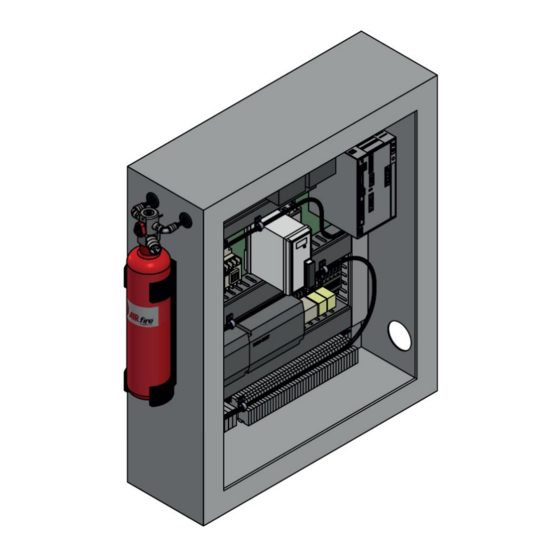
Page 37: Annex 1 - System Layout
ANNEX 1 – SYSTEM LAYOUT Technical Users Manual ARMANfire Cabinets FK-5-1-12 – TUMARFCABFK5EN – V1.1 – Date: 29/04/2020 Page 36 of 46... -
Page 38: Annex 2 - Fk-5-1-12 Features
P233: Keep container tightly closed in a cool/well-ventilated place ANNEX 2 – FK-5-1-12 FEATURES P260: Do not breathe dust/fumes/gas/vapours/spray P273: Avoid release to the environment P280: Wear protective gloves/protective clothing/eye SECTION 1: IDENTIFICATION OF THE SUBSTANCE/MIXTURE / protection/face protection UNDERTAKING P305+351+338 IF IN EYES: Rinse cautiously with water for several Product identifier minutes. - Page 39 Eyes contact Immediately flush with large amounts of water for to disperse or exhaust vapours, in accordance with good at least 15 minutes Get medical attention if irritation occurs industrial hygiene practice. Refer to other sections of this SDS for Ingestion DO NOT induce vomiting unless instructed to do so information regarding physical and health hazards, respiratory...
- Page 40 If a component is disclosed in section 3 but does not appear in If thermal degradation products are expected, use a full the table below, an occupational exposure limit is not available facepiece supplied-air respirator. for the component. Ingredient C.A.S. No. Agency Limit type Additional Comments SECTION 9: PHYSICAL AND CHEMICAL PROPERTIES 9.1.
- Page 41 10.2. Chemical stability Ingestion: Stable. May be harmful if swallowed. 10.3. Possibility of hazardous reactions SECTION 12: ECOLOGICAL INFORMATION Hazardous polymerization will not occur. 10.4. Conditions to avoid Ecotoxicological information Light 10.5. Incompatible materials Test Organism Test Type Result Strong bases Green algae, Selenastrum capricornutum 72 hours Effect Concentration Amines 50% 7.7 mg/l...
- Page 42 disposed of as hazardous wastes unless otherwise defined by applicable waste regulations. Consult with the respective regulating authorities to determine the available treatment and disposal facilities. EPA Hazardous Waste Number (RCRA): Not regulated SECTION 14: TRANSPORT INFORMATION UN, IMDG, IATA No. UN 3296 UN, IMDG, IATA proper shipping name Heptafluoropropane (Refrigerant Gas, R 227)
-
Page 43: Annex 3 - Training Programme
A test is carried out at the end of the course so to confirm all concepts are understood and validate Installers training, along with the delivery of a numbered certificate. Record of test papers and copies of certificates are maintained by AIRfire for auditing purposes carried out by LPCB. -
Page 44: Annex 4 - Service And Maintenance Check List
ANNEX 4 – SERVICE AND MAINTENANCE CHECK LIST This table shall be filled out and sent to AIRfire for its records of the system supplied General features Installation location Installation company Installation date Name of installation Chemical agent type engineer... -
Page 45: Annex 5 - Caution Label For Protected Enclosure
ANNEX 5 – Caution label for protected enclosure Compulsory to be installed on all enclosures protected by an ARMANfire system. Figure 31 - Caution label Technical Users Manual ARMANfire Cabinets FK-5-1-12 – TUMARFCABFK5EN – V1.1 – Date: 29/04/2020 Page 44 of 46... -
Page 46: List Of Figures
List of figures Figure 1 - Ball valve position Figure 2 - Cylinder layout Figure 3 - Compensation volume Figure 4 - Cylinder valve Figure 5 - Easydetect sensor tube Figure 6 - Easydetect tube fittings Figure 7 - ARMANfire bracket Figure 8 –...
Need help?
Do you have a question about the ARMANfire FK-5-1-12 and is the answer not in the manual?
Questions and answers