Table of Contents
Advertisement
Quick Links
Advertisement
Chapters
Table of Contents

Summary of Contents for Anerma Electronics Volt1000
- Page 1 Electronics User Manual Modular Power Meter Volt1000 RoCo2000AN Cube1000AN Spark5A Modular power meter with MODBUS interface for power distribution systems PJ201 Version 1.0 Anerma Electronics bv 25, Schaapsdries 2260 Westerlo Belgium Europe www.anerma.be...
- Page 2 Modular Power Meter Revision History Version Date Improvement 12 Aug-2020 Initial version 30 Nov-2020 Revision 8 Feb-2021 Extended description of the modbus registers 27 Apr-2021 Added energy counters to the modbus registers 23 Jul-2021 Major soft- and hardware review RoCo2000AN or Cube1000AN can act as router MODBUS register map is changed Spark5A sensor is added Modular power meter version 1.0...
- Page 3 Modular Power Meter Limited Warranty and disclaimer Anerma products are guaranteed to be free of defects in workmanship or materials. Any product that proves to be defective will be replaced or repaired at the discretion of Anerma. LIMITATION This limited warranty only covers conditions resulting from normal use of products. Anerma's warranty shall not apply to the following products: products or parts repaired, altered or modified by other than Anerma or an authorized repair representative, failure to follow proper installation, operation or maintenance instructions and damage resulting from improper...
-
Page 4: Table Of Contents
Chain Configuration ..................10 5.3. RTU cable ......................10 5.4. Interconnection or meter bus cables ..............11 5.5. Volt1000 ......................11 5.6. RoCo2000AN 4 channel current sensor .............. 12 5.7. Cube1000AN 4 channel current sensor .............. 12 5.8. Spark5A 3 x 5A + partial discharge sensor............13 5.9. - Page 5 Modular Power Meter 8.1. Volt1000 ......................38 8.2. Cube1000AN/RoCo2000AN ................38 List of figures .................... 39 List of Tables ..................... 40 Modular power meter version 1.0 Page 5 / 40...
-
Page 6: Purpose
Modular Power Meter 1. Purpose This document describes the use and the functional specifications of the modular power meter sensors. This is identified by Project-ID PJ201. 2. Intended Audience The intended audience is generally anybody who wants to measure power distribution systems. -
Page 7: Safety Regulations
Modular Power Meter 4. Safety Regulations 4.1. Warning, caution and notes Warnings, cautions and notes within this manual will be used as follows: WARNING: Used to denote a danger to personnel of serious injury and/or death. The warning will be preceded by the caption WARNING and the detail of any warning will be in bold and uppercase. -
Page 8: Instrument Description
In other words, for up to 15 3-phase+N outgoing power lines, it is possible to measure the voltage, current and power for the 3 phases and the voltage & current in the Neutral. To accomplish this, the Volt1000 meter samples the voltage and sends the samples to the Cube1000AN/RoCo2000AN meters on the cascade bus. Each Cube1000AN/RoCo2000AN meter uses these samples to calculate the power components. -
Page 9: Configurations
Modular Power Meter 5.1. Configurations. Different configurations are possible, hereunder we show some as an indication. SENSOR_0 SENSOR_1 SENSOR_2 SENSOR_3 SENSOR_4 Master Volt- RoCo- RoCo- RoCo- RoCo- (PLC) 2000AN 2000AN 2000AN 2000AN 1000 MODBUS RTU BUS Figure 5-2 Volt sensor act as bridge from MODBUS to sensor bus SENSOR_0 SENSOR_1 SENSOR_2... -
Page 10: Chain Configuration
MODBUS-RTU master. The first module will be seen on the configured MODBUS address while the successors will have consecutive addresses. Figure 5-6 Volt1000, Cube1000AN & RoCo2000AN chain Configuration 5.3. MODBUS-RTU cable This RTU cable, available in an order, has a standard length of 5m and with the cores of the free end freed over 50mm and stripped and tinned over 5mm. -
Page 11: Interconnection Or Meter Bus Cables
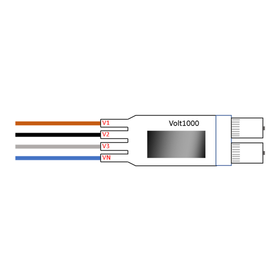
Warning: do not plug the RJ45 jack into a computer or ethernet switch, the 24V can damage the 1G-bit channel. 5.5. Volt1000 Figure 5-8 Volt1000 Module The voltage sensor has the following properties: measure 3-phase voltage +N (connection for 3 phases and neutral wire);... -
Page 12: Roco2000An 4 Channel Current Sensor
Modular Power Meter 5.6. RoCo2000AN 4 channel current sensor Figure 5-9 Current module with Rogowski coils The current sensor with 4 Rogowski coils, has the following properties: measurement coils for 4 currents (3 phases and neutral wire); modbus interface. Two RJ45 sockets for chaining. DIN-rail-TS35 mounting + magnet to fix it on an iron plate. -
Page 13: Spark5A 3 X 5A + Partial Discharge Sensor
5.10. Display with Touch Interface The Volt1000 module has a display with touch interface. This allows to view the main measurements and to alter the modbus settings. There are several screens with measurements:... -
Page 14: Ordering Codes
PC program ModbusLink, see chapter 7); writing the upgrade with our proprietary protocol over MODBUS; In a chain, the Volt1000 or first current meter can forward its upgrade to the attached Cube1000AN/RoCo2000AN/Spark5A meters. This has to be initiated via the display. -
Page 15: Modbus Interface
The first sensor is the only one that is directly connected to the modbus. It acts as a router for the chained Cube1000AN/RoCo2000AN meters so all meters can be reached from the modbus. Example A Volt1000 meter with address 10 has 3 Cube1000/RoCo2000 meters attached to it. The bus addresses are: Volt1000: 10 first Cube1000/RoCo2000: 11... -
Page 16: Register Overview
Modular Power Meter 64-bit number (int64): The MSB always comes first, or register n contains bit 63..48, register n+1 contains bit 47..32, register n+2 contains bit 31..16 and register n+3 contains bit 15..0 Date = 32-bit number that contains the offset from 1/1/2000 in seconds. o Ex1: 10 =>... - Page 17 Modular Power Meter reactive power measurements (Q) cos(φ) measurements (Cosphi) power factor measurements (PF) current distortion measurements (Ithd) apparent power measurements (S) For all these measurements, several values are available: actual value in 32-bit floating point, the actual value is the value measured in the last second actual value in 16-bit floating point mean value in 16-bit floating point over the last interval...
-
Page 18: Table 6-2 Modbus Master Table Overview
Modular Power Meter 0x3500-0x35FF Ithd 0x3600-0x36FF 0x3700-0x37FF Minimum value float16 U, Uthd, F 0x4000-0x40FF 0x4100-0x41FF 0x4200-0x42FF 0x4300-0x43FF Cosphi 0x4400-0x44FF 0x4500-0x45FF Ithd 0x4600-0x46FF 0x4700-0x47FF Table 6-2 Modbus master table overview Name Register Description Units Format Address 0x0000 Phase voltage L1 Vrms float32 0x0002 Phase voltage L2... - Page 19 Modular Power Meter P15.4 0x0276 Real power sensor 15 channel 4 float32 Q1.1 0x0300 Reactive power sensor 1 channel 1 float32 Q1.2 0x0302 Reactive power sensor 1 channel 2 float32 Q1.3 0x0304 Reactive power sensor 1 channel 3 float32 Q1.4 0x0306 Reactive power sensor 1 channel 4 float32...
-
Page 20: Table 6-3 Modbus Master Table Registers - Actual Values In Float32
Modular Power Meter Ithd15.3 0x0674 Current distortion sensor 15 channel 3 float32 Ithd15.4 0x0676 Current distortion sensor 15 channel 4 float32 S1.1 0x0700 Apparent power sensor 1 channel 1 float32 S1.2 0x0702 Apparent power sensor 1 channel 2 float32 S1.3 0x0704 Apparent power sensor 1 channel 3 float32... - Page 21 Modular Power Meter P2.2 0x1204 Real power sensor 2 channel 2 float16 P2.3 0x1205 Real power sensor 2 channel 3 float16 P2.4 0x1206 Real power sensor 2 channel 4 float16 0x1207 P15.1 Real power sensor 15 channel 1 float16 P15.2 0x1238 Real power sensor 15 channel 2 float16...
-
Page 22: Table 6-4 Modbus Master Table Registers - Actual Values In Float16
Modular Power Meter Ithd2.1 0x1603 Current distortion sensor 2 channel 1 float16 Ithd2.2 0x1604 Current distortion sensor 2 channel 2 float16 Ithd2.3 0x1605 Current distortion sensor 2 channel 3 float16 Ithd2.4 0x1606 Current distortion sensor 2 channel 4 float16 0x1607 Ithd15.1 Current distortion sensor 15 channel 1 float16... - Page 23 Modular Power Meter P1.2 0x2200 Real power sensor 1 channel 2 float16 P1.3 0x2201 Real power sensor 1 channel 3 float16 P1.4 0x2202 Real power sensor 1 channel 4 float16 P2.1 0x2203 Real power sensor 2 channel 1 float16 P2.2 0x2204 Real power sensor 2 channel 2 float16...
-
Page 24: Table 6-5 Modbus Master Table Registers - Mean Values
Modular Power Meter Ithd1.1 0x253B Current distortion sensor 1 channel 1 float16 Ithd1.2 0x2600 Current distortion sensor 1 channel 2 float16 Ithd1.3 0x2601 Current distortion sensor 1 channel 3 float16 Ithd1.4 0x2602 Current distortion sensor 1 channel 4 float16 Ithd2.1 0x2603 Current distortion sensor 2 channel 1 float16... - Page 25 Modular Power Meter I15.2 0x3138 Current sensor 15 channel 2 Arms float16 I15.3 0x3139 Current sensor 15 channel 3 Arms float16 I15.4 0x313A Current sensor 15 channel 4 Arms float16 P1.1 0x313B Real power sensor 1 channel 1 float16 P1.2 0x3200 Real power sensor 1 channel 2 float16...
-
Page 26: Table 6-6 Modbus Master Table Registers - Maximum Values
Modular Power Meter PF15.1 Power factor sensor 15 channel 1 float16 PF15.2 0x3538 Power factor sensor 15 channel 2 float16 PF15.3 0x3539 Power factor sensor 15 channel 3 float16 PF15.4 0x353A Power factor sensor 15 channel 4 float16 Ithd1.1 0x353B Current distortion sensor 1 channel 1 float16 Ithd1.2... - Page 27 Modular Power Meter I2.3 0x4105 Current sensor 2 channel 3 Arms float16 I2.4 0x4106 Current sensor 2 channel 4 Arms float16 0x4107 I15.1 Current sensor 15 channel 1 Arms float16 I15.2 0x4138 Current sensor 15 channel 2 Arms float16 I15.3 0x4139 Current sensor 15 channel 3 Arms...
-
Page 28: Individual Table - Measurements
Modular Power Meter PF2.2 0x4504 Power factor sensor 2 channel 2 float16 PF2.3 0x4505 Power factor sensor 2 channel 3 float16 PF2.4 0x4506 Power factor sensor 2 channel 4 float16 0x4507 PF15.1 Power factor sensor 15 channel 1 float16 PF15.2 0x4538 Power factor sensor 15 channel 2 float16... -
Page 29: Individual Table - Info
Modular Power Meter U3thd 0x5012 Total harmonic distortion – U3 float32 Frequency 0x5014 Frequency float32 Rotation 0x5016 field float32 0x5018 Current channel 1 Arms float32 0x501A Current channel 2 Arms float32 0x501C Current channel 3 Arms float32 0x501E Current channel 4 Arms float32 0x5020... -
Page 30: Settings Table
Table 6-11 Modbus command registers 6.3.8. Energy table – Integers The Volt1000 sensor counts the energy for every input of every current sensor (4 inputs per sensor). There are 4 counters for every input: consumed real energy injected real energy positive reactive energy negative reactive energy. - Page 31 Modular Power Meter All counters are available per input (labeled “Exxx”) and per sensor (labeled “ESxxx”). The values per sensor add together the values for the 4 inputs for that sensor. Name Register Description Units Units Address Econsumed-ch1 0x6000 Consumed real energy for Joule int64 sensor 1 channel 1...
-
Page 32: Table 6-12 Modbus Energy Counter Registers - Int64
Modular Power Meter sensor 15 channel 4 Eqtot-ch1 0x6800 Total reactive energy for Joule int64 sensor 1 channel 1 Eqtot-ch2 0x6804 Total reactive energy for Joule int64 sensor 1 channel 2 Eqtot-ch60 0x68EC Total reactive energy for Joule int64 sensor 15 channel 4 Eqpos-s1 0x6900 Positive reactive energy for sensor 1... -
Page 33: Table 6-13 Modbus Energy Counter Registers - Float32
Modular Power Meter Einjected-s1 0x7400 Injected real energy for sensor 1 float32 Einjected-s2 0x7402 Injected real energy for sensor 1 float32 Einjected-s15 0x741C Injected real energy for sensor 15 float32 Etotal-s1 0x7500 Total real energy for sensor 1 float32 Etotal-s2 0x7502 Total real energy for sensor 1 float32... -
Page 34: Protocol Functions
The new baudrate and address settings are saved immediately in the sensor permanent memory. If, and only if, the Volt1000 sensor is the only one on the MODBUS-bus, then you can use 0 (zero) as a special serial number, that is always accepted. -
Page 35: Table 6-14 Modbus Settings Packet
Modular Power Meter Byte Value Description 0..17 This is an 18-bytes password, if this password is correct then the MOBUS address is neglected. It’s a good idea to use the new modbus address already in the packet. Baudrate communication settings 0=4800 1=9600 2=19200... - Page 36 Modular Power Meter This example contains the packet with the following parameters: the meter serial number is 2029004 (0x001EF5CC) baudrate 38400 (communication setting=0x03) address 13 (0x0D) The resulting packet is (the 3 parameters are underlined): 00 17 FE FF 00 01 FF 03 00 09 12 B5 7E 3A 1D C8 F9 00 03 00 13 00 00 00 1E F5 CC 00 0D F5 DE Alternatively, this works also with the target address 13 (OD): 0D 17 FE FF 00 01 FF 03 00 09 12 B5 7E 3A 1D C8 F9 00 03 00 13 00 00...
-
Page 37: Modbuslink
Modular Power Meter 7. ModbusLink ModbusLink is a PC program that can be used to control the sensors. A USB-RS485 cable is required to connect to the sensors. The program has a user interface at the top and an information window below. This includes an option to show all modbus communication. There are 3 main functions: Read registers: Either read a selected number of registers starting at a selected address or use a command file to initiate multiple read operations. -
Page 38: Specifications
8. Specifications 8.1. Volt1000 Specification physical dimensions Units Value Housing W x H x D 92 x 36,5 x 30 Table 8-1 Volt1000 Mechanical Specification Volt1000 meter Units Value Minimum supply voltage 4,5 (*15) Maximum supply voltage Typical power consumption @24V... -
Page 39: List Of Figures
Figure 5-4 Sensors can be mixed, but Volt must be first and Spark must be the last ..9 Figure 5-5 Volt or RoCo can be used as a single device ........... 9 Figure 5-7 Volt1000, Cube1000AN & RoCo2000AN chain Configuration ......10 Figure 5-6 MODBUS RTU cable pinning ................ 10 Figure 5-9 Volt1000 Module .................. -
Page 40: List Of Tables
Table 6-13 Modbus energy counter registers – float32 ..........33 Table 6-14 Modbus settings packet ................35 Table 6-15 Modbus settings response ................. 35 Table 8-1 Volt1000 Mechanical ..................38 Table 8-2 Volt1000 Electrical ..................38 Table 8-3 Cube1000AN/RoCo2000AN Mechanical ............38 Table 8-4 Cube1000AN/RoCo2000A Electrical ...............
Need help?
Do you have a question about the Volt1000 and is the answer not in the manual?
Questions and answers