
Summary of Contents for Himel HTND2 Series
- Page 1 HTND Series User Manual Please carefully read the user manual before the installation and use of the products,and then keep it properly as backup.
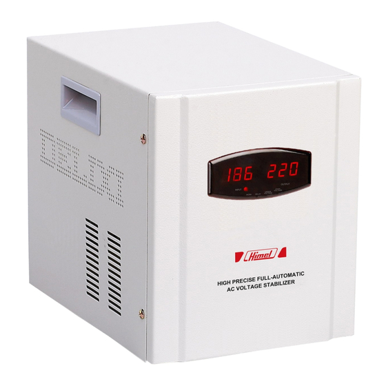
- Page 2 High Precise Full-Automatic AC Voltage Stabilizer Overview 1. HTND series is a new developed LED display AC voltage stabilizer based on HTND. It is controlled by CPU, while it has elegant appearance, wide range for stabilizing voltage and no additional distortion. Overvoltage protection and short circuit protection are included in HTND (undervoltage protection and time-delay selection can be customized).
-
Page 3: Main Technical Parameters
Main Technical Parameters 1. Main Technical Parameters Pole Single-Phase Item Input Voltage Range 150V~250V 220V Output Voltage 246±4V Output Overvoltage <±4% Output Voltage Precision Frequency 50/60Hz <80K Temperature Rise >92% Efficiency <1s(when variation of input voltage is 10 %) Regulation Time Note 1:... - Page 4 2. Output Capacity Curve P/Pe 100% Capacity curve: Where Output 220V Fig.1: output capacity curve; P: output capacity; Pe: rated output capacity; Capacity curve: U: input voltage; Output 110V&220V Ux: lower limit value of input voltage allowed; Us: upper limit value of input voltage allowed. Ux 198 220 U(Input voltage:V) Fig.1 Output Capacity Curve...
- Page 5 2 HTND series LED Working Mode Display 150 220 INPUT OUTPUT WORK OVER DELAY UNDER VOLTAGE VOLTAGE Fig.3 Fig.3 HTND2-LED Display LCD Display Working Mode: 1. LED panel (lens); 2. Input Voltage; 3. Output Voltage; 4. Working Indicator; 5. Time-delay Indicator; 6.
- Page 6 4 HTND -2kVA End Panel Appearance OUTPUT 220V HIGH PRECISE FULL-AUTOMATIC AC VOLTAGE STABILIZER HTND -2000VA Model: Max.2000VA Output rating: Input voltage: 150V~250V AC Frequency: 50Hz/60Hz 110V Output voltage: ±4% 220V Number of phase: Insulation grade: Fig.5 End Panel Part Where 1.
-
Page 7: Electric Diagram
6 HTND -7kVA ~10kVA End Panel Appearance OUTPUT 220V HIGH PRECISE FULL-AUTOMATIC AC VOLTAGE STABILIZER HDB3W Model: HTND -10kVA Output rating: Max.10kVA Input voltage: 150V~250V AC Frequency: 50Hz/60Hz Output voltage: 220×(1±4%)V AC Number of phase: Insulation grade: THE MAXIMUM OUTPUT CURRENT OF 10A SOCKET! Fig.7 End Panel Part Where 1. - Page 8 2 Single-phase 1kVA~10kVA Electric Block Diagram. sampling control circuit Output Input Fig.9: 1kVA~10kVA Electric Block Diagram 3 Single-phase 15kVA~30kVA Electric Block Diagram Using Compensation Circuit. sampling control Input Output circuit Fig.10: Single-phase 15kVA~30kVA Electric Block Diagram Electric Diagram 1 The nominal power of the voltage stabilizer is maximum apparent power, however, the nominal power of the household appliances is active power, e.g.
- Page 9 input voltage is too low, load shall be decreased, and details for selection can follow the capacity curve (Fig.1). 2 If stabilizer uses 110V as the output voltage, the output capacity shall not exceed 35% of rated capacity in order to avoid being damaged from overload.
- Page 10 246V±4V due to its own problem, the overvoltage indicator will flash and alarm, and then power supply will be cut off after 10 to 15 seconds time-delay. 7 When the output load exceeds the integrated rated load or output is short circuit, the power switch will trip for protection and cut off the power supply.
- Page 11 12 Our product has input/output connecting terminals and output socket. According to product power, suitable conductive wires can be selected for input/output wires following No.10 “installation trip” in the user manual. 13 Phase line, neutral line and grounding line are wiring following the product marking in order to avoid being electrified on the output after power-off.
-
Page 12: Common Faults And Troubleshooting
where is ventilate, dry, no direct sunlight and no erosive gas; e) Output side cannot be used in parallel. 1.4 Relative Humidity Relative humidity shall not exceed 90% (When temperature is 25℃). 2 Power supply shall be disconnected regularly (generally 6 months or 1 year) according to application environment. - Page 13 engineers to avoid electric shock accidents or voltage stabilizer damage. Table 1: Common Faults and Troubleshooting Failure Phenomenon Failure Reason Troubleshooting 1. Input of the stabilizer is 1. Power on the input power and Voltage stabilizer is out open circuit; check whether the wiring is solid and of work and no output 2.
-
Page 14: Installation Tips
Installation Tips Proper external wiring conductive lines are selected according to load power or rated power of voltage stabilizer before installation. Input and output conductive lines for external wiring is not recommended to be too thin or too long to cause abnormal work. External wiring conductive lines can be selected as follows: As calculation of a standard current-carrying capacity for a copper conductor: the safe current-carrying capacity... - Page 16 HIMEL www.himel.com Copyright@himel Co,.Ltd. Paper can be recycled Apr.2018...
Need help?
Do you have a question about the HTND2 Series and is the answer not in the manual?
Questions and answers