Advertisement
Quick Links
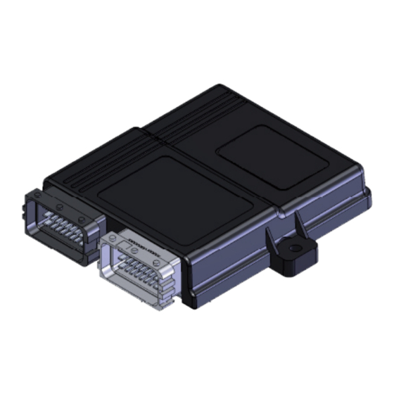
4 CYL. INJECTION CONTROL UNIT
INSTALLATION MANUAL
Specifiche tecniche / Technical specifications
Tensione di alimentazione / Supply voltage
Temperatura di funzionamento / Operating temperature
Fusibile di protezione / Protection fuse
Assorbimento di corrente con attuatori disattivi / Current absorption
with the actuators disabled
Assorbimento di corrente in modalità standby / Current absorption
in standby mode
Attuatori gestiti / Actuators managed
Uscita fili elettrovalvole gas / Wire output gas solenoid valves
AUTOMOTO SEQUENTIAL SYSTEMS
T-2/188 MANGOLPURI INDUSTRIAL AREA
110083 - PHASE-1, NEW DELHI, INDIA
PC
Vbat= 10÷16V
-40÷105°C
MAX 15A
Imax ≤0.5A
Istandby ≤10 mA
Fino a 4 iniettori con caratteristiche:
Imax= 6A, Vbat max= 16V
up to 4 injectors with the following characteristics:
Imax= 6A, Vbat max= 16V
Pmax= 25W, Imax= 2A (potenza e corrente mas-
sima per ogni uscita con due uscite attive)
-----------------------------------------------------
Pmax= 50W, Imax= 4A (potenza e corrente mas-
sima con solo una uscita attiva)
Pmax= 25W, Imax= 2A (power and maximum cur-
rent for each output with two outputs enabled)
-----------------------------------------------------
Pmax= 50W, Imax= 4A (power and maximum
current with just one output enabled)
AVVERTENZE GENERALI/GENERAL INFORMATION
Where to install the control unit:
Dove fissare la Centralina /
- LONTANO da possibili INFILTRAZIONI D'ACQUA.
- FAR from any WATER LEAKAGE
- LONTANO da ECCESSIVE FONTI DI CALORE (esempio collettori di scarico).
- FAR from EXCESSIVE HEAT SOURCES (such as exhaust manifolds).
- LONTANO dai CAVI DELL'ALTA TENSIONE.
- FAR from HIGH-VOLTAGE CABLES.
Fare delle buone connessioni elettriche evitando l'uso dei "RUBACORRENTE".
S i t e n g a p r e s e n t e c h e l a m i g l i o r e c o n n e s s i o n e e l e t t r i c a è l a s a l d a t u r a
debitamente isolata.
Create efficient electrical connections without using any "POWER TAPS".
Properly insulated soldering is the most effective type of electrical connection.
Avvisare il cliente che in caso di rottura del fusibile dell'impianto a GAS, il Sistema ripri-
stina i collegamenti dei dispostivi a cui è collegato. Si sconsiglia
vivamente di sostituire il fusibile con un'altro di amperaggio maggiore, cio' puo' provo-
care danni irreparabili.
Advise the customer that if the GAS system fuse burns, the connections of the devices
to which it is connected will be restored. It is strongly recommended not to replace the
fuse with another one with a higher amperage rating since it may cause irreparable
damage.
Non aprire per nessun motivo la scatola della Centralina soprattutto con il motore in
moto o il quadro inserito, onde evitare danni irreparabili.
AUTOMOTO SEQUENTIAL SYSTEMS
derivati dalla manomissione del proprio dispositivo da parte di personale non autorizzato
con la conseguente perdita di GARANZIA.
Do not open the Control Unit box for any reason, especially when the engine is running or the key
is in the ignition, to avoid irreparable damage.
AUTOMOTO SEQUENTIAL SYSTEMS
injuries to persons if unauthorised personnel tamper with its devices; such tampering
will also invalidate the WARRANT
Come fissare la Centralina/ How to install the Control Unit
INSTALLAZIONE
ERRATA
INCORRECT
INSTALLATION
616000126 Rev. 110313-0
Il presente documento non può essere riprodotto né portato a conoscenza di terzi senza autorizzazione della ditta AUTOMOTO.
This document may not be reproduced or made known to any third party without permission of the company AUTOMOTO.
declina ogni responsabilità per danni a cose e persone
will not be held responsible for damage to property or
Y.
INSTALLAZIONE
INSTALLAZIONE
ERRATA
CORRETTA
INCORRECT
CORRECT
INSTALLATION
INSTALLATION
2-10
Advertisement

Summary of Contents for automoto PC
- Page 1 616000126 Rev. 110313-0 2-10 Il presente documento non può essere riprodotto né portato a conoscenza di terzi senza autorizzazione della ditta AUTOMOTO. This document may not be reproduced or made known to any third party without permission of the company AUTOMOTO.
- Page 2 Il presente documento non può essere riprodotto né portato a conoscenza di terzi senza autorizzazione della ditta Automoto. This document may not be reproduced or made known to any third party without permission of the company Automoto. This document may not be reproduced or made known to any third party without permission of the company Automoto.
- Page 3 VERDE NERO aspirazione MASSA INGRESSO GAS ATTENZIONE! Rispettare la sequenza dei INGRESSO SEGNALE VIOLA VISUALIZZAZIONE A PC VALORI collegamenti, i fili BLU e FUNZIONAMENTO SONDA LAMBDA INIETTORI BLU-NERO devono BENZINA essere in corrispondenza dell’iniettore gas marcato A, COLLETTORI gli altri di seguito come in D’ASPIRAZIONE...
- Page 4 RAIL INJECTORS TO INTAKE GREEN BLACK MANIFOLD GAS INLET VIOLET WARNING! SIGNAL INPUT USED TO DISPLAY THE SENSOR VALUES ON THE PC THE CONNECTOR OF THE GAS INIETTORI INJECTOR MUST BENZINA CORRESPOND TO THE BLUE WIRE OF THE PETROL BLUE...
- Page 5 Il presente documento non può essere riprodotto né portato a conoscenza di terzi senza autorizzazione della ditta Automoto. This document may not be reproduced or made known to any third party without permission of the company Automoto. This document may not be reproduced or made known to any third party without permission of the company AUTOMOTO.
Need help?
Do you have a question about the PC and is the answer not in the manual?
Questions and answers