Advertisement
Quick Links
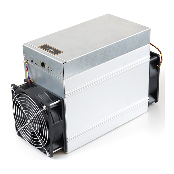
Instructions for S9K S9SE Maintenance
Editor-in-Chief: Wang Penghua
Version date: 2019.7.9
File Category: Maintenance Plan
Content of this Volume: It mainly describes the troubleshooting of various faults of S9K S9SE, and how to use the test tool for accurate positioning.
1. The constant temperature soldering iron (350-400°C). The tip soldering iron head is used for soldering chip resistors and capacitors.
2. The thermal chimney is used for chip disassembly and soldering, be careful not to heat for a long time to avoid PCB foaming.
3. APW3 + + power supply (output 12V, 133A Max), used for test and measurement of the computing board.
4. The multimeter, tweezers, V9 test jig (if there is condition, an oscilloscope can be configured).
5. Flux, water for cleaning panel with anhydrous alcohol; water for cleaning panel is used to clean flux residue and appearance after maintenance.
7. Thermally conductive adhesive is used to re-attach the cooling fin after repair.
1. The maintenance personnel must have certain electronic knowledge, more than one year of maintenance experience, and master QFN package welding
technology.
2. After repair, the computing board must be tested twice and confirmed as OK before it can pass!
3. Pay attention to the operation method when replacing the chip. After replacing any accessories, the PCB board is not obviously deformed, and the replaced
parts and the surrounding area shall be checked for whether there is open and short circuit.
4. Determine the maintenance station object and the corresponding test software parameters and test jigs.
5. Check whether the tools and jigs can work normally.
(Whether the power output is the same as the setting in the jig config file. Different BIN level and chip package mode need to correspond to the config and
single-board-test files of the single board test jig program.)
1. Principle overview
1. S9K S9SE computing board is composed of 6 voltage domains connected in series. There are 10 BM1393 chips in each voltage domain, and there are 60
BM1393 chips on the whole board.
2. There are 208 cores on a single BM1393 chip, the domain voltage is 1.6V, and the total voltage of the 6 domains on the whole board is 9.6V-9.9V
3. S9K S9SE clock is composed of two 25M active crystal oscillators (Y1, Y2), Y1 is transmitted from the first chip to the 30th chip in series, and Y2
is transmitted from the 31st chip to the 60th chip in series
4. There is independent small cooling fin on the front and back of each chip of the S9K S9SE computing board. The small cooling fin on the front side is the
SMT patch, and the small cooling fin on the back side is fixed on the back of the IC by the thermally conductive adhesive after the initial measurement. After
the repaired and replaced chip passes the test, it is necessary to evenly apply black thermally conductive adhesive on the IC surface and heat and fix it.
Note:
In the maintenance process, when replacing the circuit board components or the chip, in order to reduce the damage of high temperature of the blower gun to
the PCB board and the chip, it is necessary to first remove the small cooling fins near the faulty component and on the back of the PCB board before
replacing.
There are test points on the PCB chip surfaces. When manufacturing and repairing, if there is no cooling fin attached on the PCB chip, the test point on the
chip surface can be used; for repair of finished products (after-sales repair), since the front and back of the PCB are covered by cooling fins, it needs to locate
fault through the test point on the chip surface of the PCB. A special slender test lead can be used to probe the cooling fin gap for measurement. However,
since the SMT small cooling fin is connected to the ground of each voltage domain, it is necessary to pay attention to the insulation of the test lead in
measurement to avoid short circuit caused by the test lead.
I. Requirements on the Maintenance Platform
II. Requirements on Maintenance Operations
III. Principle and Structure
1
S9k S9SE Maintenance Guide
Advertisement

Summary of Contents for ASIC Bitmain Antminer S9K
- Page 1 S9k S9SE Maintenance Guide Instructions for S9K S9SE Maintenance Editor-in-Chief: Wang Penghua Version date: 2019.7.9 File Category: Maintenance Plan Content of this Volume: It mainly describes the troubleshooting of various faults of S9K S9SE, and how to use the test tool for accurate positioning. I.
- Page 2 S9k S9SE Maintenance Guide 2. Analysis of key point 2.1 The following figure shows the chip domain distribution, signal path and circuit distribution of the S9K S9SE signal board: DC 输入口 DC-DC 钳位电路 域 1 IO 座 J4 域电压信号 电平转换 IC EEPROM 芯片...
- Page 3 S9k S9SE Maintenance Guide 钳位电路输出端 EC39 为 3.5V 钳位电路输出端 EC39 为 3.5V Clamping circuit output EC39 is 3.5V The flow direction of CLKO signal is generated by Y1 25M crystal oscillator, which is transmitted from chip U1 to chip U30; it is generated by Y2 25M crystal oscillator, and is transmitted from chip U31 to chip U60.
- Page 4 S9k S9SE Maintenance Guide 2.2.2 Schematic diagram of DC to DC circuit 2.2.3 Schematic diagram of EEPROM IC (single board test will change the magic number, temperature sensing information and CRC information in the EEPROM) 2.2.4 Schematic diagram of clamping circuit...
- Page 5 S9k S9SE Maintenance Guide 2.2.5 Schematic diagram of PIC U102 2.2.6 Signal test points of each chip (as shown below after amplified):...
- Page 6 S9k S9SE Maintenance Guide 域 1、3、5 信号测试点 域 2、4、6 信号测试点 域 1、3、5 信号测试点: Signal test points in Domain 1, 3, 5 域 2、4、6 信号测试点: Signal test points in Domain 2, 4, 6 2.2.7 Pin circuit diagram of each chip in Domain 1, 3, and 5...
- Page 7 S9k S9SE Maintenance Guide 2.2.8 Pin circuit diagram of each chip in Domain 2, 4, and 6 2.2.9 Circuit diagram of J4 at IO port...
- Page 8 S9k S9SE Maintenance Guide 2.2.10 0.8V, 1.8V circuit schematic diagram 2.2.11 Schematic diagram for Level signal conversion...
- Page 9 S9k S9SE Maintenance Guide 2.2.12 Schematic diagram for Y1, Y2 crystal oscillator 2.2.13 LDO 0.8V, 1.8V and crystal oscillator measurement...
- Page 10 S9k S9SE Maintenance Guide ● S9K S9SE maintenance ideas During the maintenance, conduct 10 tests before and after the main test chip (five before and after the chip: CLKO, CO, RI, BO, NRSTO); DC-DC output and PIC voltage CORE voltage; LDO (0.8V 1.8V), PLL-0.8V. Detection method: 1) When the IO line is not inserted and only 12V is inserted: the DC-DC output is about 0V, and the boost output is about 0V.
- Page 11 S9k S9SE Maintenance Guide ●PCBA label diagram ● Description of chip correspondence IV. Routine Maintenance Process Reference steps: Observe the appearance According to Locate the chip, Check each test Measured the detection reweld first, and point impedance information Voltage and replace if reweld is Test Locate fault...
-
Page 12: Fault Type
S9k S9SE Maintenance Guide V. Fault Type Common fault types of the S9K S9SE computing board: 1. Cooling fin falls, shifts and deforms The cooling fin on the PCB board on the back of the computing board chip is not allowed to shift or collide before power on, especially the cooling fin with different voltages. -
Page 13: Maintenance Instructions
S9k S9SE Maintenance Guide VI. Maintenance Instructions 1. During maintenance, the maintenance personnel must be familiar with the function and flow direction of each test point, the normal voltage value and the impedance value to ground. 2. Must be familiar with the chip soldering, so as not to cause PCB foaming deformation or pin damage. 3.
Need help?
Do you have a question about the Bitmain Antminer S9K and is the answer not in the manual?
Questions and answers