Advertisement
Quick Links
Advertisement

Summary of Contents for AudioStak ProSwitch PRSW-MCU-PCB
- Page 1 ProSwitch Manual and Installation Guide...
- Page 2 Overview Introduction ProSwitch modules are used to create interactive product demonstration displays which can be intuitively operated by a salesperson or customer without instruction or special technical knowledge. ProSwitch modules switch low level (RCA), high level or high current (ie subwoofers and high power amplifiers) signals, and can be combined to create scalable audio/video systems from small stand-alone displays to large car-audio rooms.
- Page 3 ProSwitch Modules ProSwitch systems are comprised of four types of modules: Main Module (PRSW-MCU-PCB): Main Modules read button presses and communicate with other Main Modules in the system. They control and synchronize ADD-ON signal modules. Each set of four components or speakers to be switched requires one Main Module. High Level ADD-ON Module (PRSW-4HL-PCB): High Level Modules (4H) switch high level signals up to 7A MAX (196 Watts for a typical 4 ohm speaker), such as speakers, head unit outputs or amplifier outputs.
- Page 4 This allows only active components to be turned on to save power and allow a smaller system power supply. This is the method recommended by AudioStak. The Active LED indicates when the module has an active position or flashes in different modes as a troubleshooting aid in the event of a wiring error or module failure.
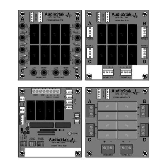
- Page 5 High Level ADD-ON Module PRSW-4HL-PCB ADD-ON Connectors Mounting Standoffs PRSW-4HL-PCB Speaker or Component High Level Signal Connectors POSN A POSN B POSN C POSN D L+ L- R+ R- L+ L- R+ R- Writing/Labelling Area Writing/Labelling Area SIGNAL BUS SIGNAL BUS Signal Bus Connectors Figure 2: High Level ADD-ON Module PRSW-4HL-PCB High Level ADD-ON Module PRSW-4HL-PCB (Figure 2) is used for switching high level signals up to 7 Amps MAX...
- Page 6 Low Level ADD-ON Module PRSW-RCA-PCB ADD-ON Connectors Mounting Standoffs PRSW-RCA-PCB Component RCA Connectors LEFT RIGHT RIGHT LEFT SIGNAL BUS SIGNAL BUS Signal Bus Connectors Figure 3: Low Level RCA ADD-ON Module PRSW-RCA-PCB Low Level ADD-ON Module PRSW-4L-PCB (Figure 3) is used for switching low level RCA signals, such as amplifier inputs or head unit RCA outputs.
- Page 7 High Current Mono ADD-ON Module PRSW-MONO-PCB ADD-ON Connectors Mounting Standoffs PRSW-MONO-PCB High Current Screw Terminals Writing/Labelling Area Writing/Labelling Area SIGNAL BUS SIGNAL BUS Signal Bus Connectors Figure 4: High Current Mono ADD-ON Module PRSW-MONO-PCB High Current Mono ADD-ON Module PRSW-MONO-PCB (Figure 4) is used for switching high current mono signals, such as sub woofers and high-power amplifier outputs, up to 16 Amps (1024 Watts for a typical 4 ohm speaker).
- Page 8 Groups In a ProSwitch system, audio/video products must be arranged into Groups of similar devices. For example, head units would be one Group, front speakers would be another. Each Group is then given a Group Number, which set through the DIP switches on the Main Modules (PRSW-MCU-PCB). ProSwitch systems can have up to 16 groups of speakers, and up to 16 groups of components.
- Page 9 Main Module Address Each Main Module has an Address which is made up of the Group Number, Board Number and device type (Component or Speaker). These are all set using the DIP switches on the Main Module, shown in Figure 5. The switch labelled 'COMP' and 'SPKR' is used to set the device type.
- Page 10 GROUP OR BOARD NUMBER: Figure 6: Setting Group or Board Numbers with Main Module DIP Switches Overview – Main Module Address...
- Page 11 COMM Bus Main Modules communicate with each other using the COMM Bus to form an integrated system. Each Main Module has two COMM Connectors: COMM In and COMM Out. The COMM Bus is wired by connecting the COMM Out of the first module to the COMM IN of the second. The COMM Out of the second module is connected to the COMM In of the third and so on, until finally the COMM Out of the last module is connected back to the COMM In of the first module to complete the COMM Bus.
- Page 12 Signal Bus Each ADD-ON module has signal connectors for each of its four Positions, as well as two sets of connectors for the Signal Bus. When a Position is active, it is connected to the Signal Bus. Using the Signal Bus connectors, the signal is carried from one ADD-ON module to the next so all are connected within its Group.
- Page 13 one head unit and one pair of speakers can be selected at a time. When a head unit is selected, it is connected to the Signal Bus for the Head Unit Group. When a speaker pair is selected, it is connected to Signal Bus for the Speaker Pair Group.
- Page 14 so these are each considered to be their own Group. Two Main Modules are needed for each Group (one per four products). The only signal which needs to be accommodated for the Head Unit Group in this sample system is the high level output so one 4H ADD-ON module is required for each Main Module. In the Speaker Group, one 4H module per Main Module is also required to switch the high level signal to the selected speaker.
- Page 15 Bypass Sometimes it may be necessary to allow an entire Group to be deselected. If this Group is inline with the signal path between two other Groups, the signal will need to be allowed to Bypass this Group. An example of this is an equalizer Group, where if no equalizer is selected, the low level output from the head unit Group should pass directly through to the amplifier Groups.
- Page 16 Head Unit Group C B M C B M GROUP GROUP BOARD BOARD C B M C B M GROUP GROUP BOARD BOARD Head LOW LEVEL Unit 1 Head Unit 2 Head Unit 5 Head Unit 6 OUTPUT LOW LEVEL BUS Head Unit 3 Head Unit 4 Head Unit 7...
- Page 17 Mute Time When some components, such as amplifiers, are turned on and off they can produce audible 'pops' and 'thumps' which are undesirable. To eliminate this, the Mute Time function can be used so speakers are temporarily muted every time a component is turned on or off. The first DIP switch on the Main Modules (see Figure 1) has two switches for setting Mute Times.
- Page 18 COMM Bus Error Modes and Troubleshooting Main Module Active LED Each time a button is pressed, the ProSwitch system checks the entire COMM Bus for proper operation. If there is a COMM Bus wiring error anywhere in the system, the Active LED on each Main Module can blink in one of three modes to assist in troubleshooting.
- Page 19 If all Main Modules in the system are flashing in Timeout Error Mode, the likely location of the error is the DATA wire from the COMM Out connector of the module that originated the data transmission. If you’re unsure of which module that was, turn the system off and back on again, and re-initiate the error condition by pressing a button connected to a different Main Module.
- Page 20 Main Module DIP Switch Settings Worksheets Group: Description: Group: Description: Settings: Settings: GROUP BOARD GROUP BOARD NUMBER NUMBER NUMBER NUMBER Group: Description: Group: Description: Settings: Settings: GROUP BOARD GROUP BOARD NUMBER NUMBER NUMBER NUMBER Main Module DIP Switch Settings Worksheet...
Need help?
Do you have a question about the ProSwitch PRSW-MCU-PCB and is the answer not in the manual?
Questions and answers