Advertisement
Advertisement

Related Manuals for All Star Wheelchairs ASW-203


Summary of Contents for All Star Wheelchairs ASW-203
- Page 1 User Manual ASW-203 Copyright © 2022 All Star Wheelchairs...
-
Page 2: Table Of Contents
Table of Contents Introduction ............................................3 Safety ..............................................5 Your Electric Wheelchair ......................................10 Assembly/Disassembly ......................................16 Controller operation ........................................20 Comfort Adjustments ......................................29 Batteries and Charging......................................35 Care and Maintenance ......................................46... -
Page 3: Introduction
Introduction Safety The power chair you have purchased combines state-of- the-art components with safety, comfort, and styling in mind. We are confident that these design features will provide you with the conveniences you expect during your daily activities. Once you understand how to safely operate and care for your power chair, it should give you years of trouble-free operation and service. - Page 4 Purchaser’s Agreement By accepting delivery of this product, you promise that you will not change, alter, or modify this product or remove or render inoperable or unsafe any guards, shields, or other safety features of this product; fail, refuse, or neglect to install any retrofit kits from time to time provided to enhance or preserve the safe use of this product.
-
Page 5: Safety
Safety Product Safety Symbols The symbols below are used on the power chair to identify warnings, mandatory actions, and prohibited actions. It is very important for you to read and understand them completely. NOTE: There are more warnings identified and explained in the Consumer Safety Guide that is included with your power chair. - Page 6 Unlocked and in freewheel mode. Class II Equipment. Power Chair information label Manufacturer Do not remove the anti-tip wheels. Not to be used as a motor vehicle seat .
- Page 7 General Guidelines MANDATORY! Do not operate your new power chair for the first time without completely reading and understanding this owner’s manual. Your power chair is a state-of-the-art life-enhancement device designed to increase mobility. We provides an extensive variety of products to best fit the individual needs of the power chair user. Please be aware that the final selection and purchasing decision regarding the type of power chair to be used is the responsibility of the power chair user, who is capable of making such a decision, and his/her healthcare professional (i.e., medical doctor, physical therapist, etc.).
- Page 8 As you begin using your power chair during daily activities, you will probably encounter situations in which you will need some practice. Simply take your time and you will soon be in full and confident control as you maneuver through doorways, on and off of lifts, up and down ramps, and over moderate terrain.
- Page 9 Check the brakes. See “Care and Maintenance.” ● Check battery charge. See “Batteries and Charging.” ● Ensure the manual freewheel levers are in drive mode before sitting on the power chair. ● NOTE: If you discover a problem, contact your authorized Provider for assistance. Safety Warnings Do not use on inclines ≥...
-
Page 10: Your Electric Wheelchair
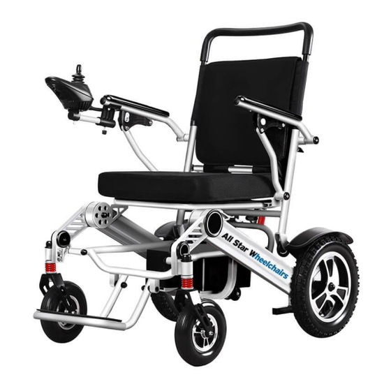
Your Electric Wheelchair ASW-203 It is a power electric wheelchair that you can easily fold for transportation or storage. The battery box slides into the rear of the chair near the base for stability of speed and direction. It is intended used in Home healthcare environment or on gentle surfaces. - Page 11 ASW-203 Figure 1: Figure 2: Figure 3:...
- Page 12 Controller Connector: This is where the controller connects to the power base. Each controller uses a different type of cable. Regardless of which type of controller is used, the cable must be secured to the assembly and not allowed to drag on the floor. Battery Box Charger Port: This enables you to charge the battery when the battery box is removed from the power base.
- Page 13 Manual Freewheel Levers For your convenience, your power chair has a manual freewheel lever on each motor. Manual freewheel levers enable you to disable the drive system in order to maneuver the chair manually. WARNING! Do not use the power chair while the drive motors are disengaged! Do not disengage the drive motors when the power chair is on an incline or decline, as the unit could roll on its own! Only engage the freewheel mode when on a level surface.
- Page 14 To engage or disengage the drive motors: Locate the lever on each motor. Push down the manual freewheel levers down to disengage the drive motors (free mode). Pull up the manual freewheel levers inward to engage the drive motors (drive mode). D: Drive Mode (Drive Engaged) N: Freewheel Mode (Drive Disengaged) WARNING! Do not use the freewheel lever handles as tie-down points to secure this product.
- Page 15 Anti-Tip Wheels The anti-tip wheels are an integral and important safety feature of your power chair. They are attached to the frame at the rear of the chair. See figures 2 PROHIBITED! Do not remove the anti-tip wheels or modify your power chair in any way that is not authorized Storage Compartments Your power electric wheelchair is equipped with one storage compartments.
-
Page 16: Assembly/Disassembly
Assembly Initial Assembly Remove the wheelchair and spare parts from its packaging. Place one hand on top of the seat backrest and push it downward . Install the controller to the right or left hand armrest of the driver. Insert the controller into the armrest and tighten the screw, then latch the quick release handle. - Page 17 NOTE: Ensure that the controller harness does not become pinched when folding and unfolding your power chair. If pinching occurs, the harness was twisted prior to installation. Uninstall and untwist the controller harness, and ensure upon reinstallation that your power chair can fold and unfold without creating harness pinch points.
- Page 18 Folding and Unfolding Your power chair can be folded for easy transportation and storage. To fold the power chair: Pull the folding and locking mechanism, to make the wheelchair unlock; Fold the foot platform upwards toward the seat of the power chair. Gently press the seat backrest forward and downward.
- Page 19 To unfold the power chair: Place one hand on top of the seat backrest,gently pull the seat backrest upward . Sit on the seat and lie down, or press the top of the seat backrest downward. Confirm the folding and locking Mechanism is locked. WARNING! To avoid injury, ensure the seat backrest is fully unfolded and the locking mechanism is engaged before sitting in your power chair.
-
Page 20: Controller Operation
Controller Operation Controller Operation: Joystick Front Control Panel Charging Port The operation of the controller Try to avoid knocking the controller, especially the joystick. Do not beat the controller and the joystick while traveling. Do not hit the controller. When operating the wheelchair, ensure that the control system is safe and reliable. - Page 21 Battery meter / electricity indicator Power switch button Horn switch button Speed limit adjustment / Driving module indicator Speed/ Driving module decrement button Speed / Driving module incremental button Switch key and battery meter Power switch button is the control form of power supply to control system. Press the power switch button once to get the power on of the control system.
- Page 22 The battery meter indicates that the electric wheelchair has been powered on, and also indicates the operation status of the electric wheelchair. Joystick The main function of the joystick is to control the speed and direction of the electric wheelchair. The farther the joystick is pushed away from the center, the faster the electric wheelchair will travel, and the automatic brake will be applied when the joystick is released.
- Page 23 Horn Button When you press the horn button, the horn sounds. Charger Socket This socket is only used for electric wheelchair charging and special programmer. This socket cannot be used as the power supply of any other electrical devices. If it is connected with other electrical devices, it may damage the control system or affect EMC performance of the electric wheelchair.
- Page 24 LED Self-diagnosis If there is a system error, calculate the amount of electricity Indicator Flashing, you can find the problem. Here is a list of self-diagnose: One light on: The battery voltage is low, the battery needs to be charged or there is something wrong with the connection.
- Page 25 Seven lights on: It indicates that the joystick is faulty. Before starting the control system, please make sure that the joystick is in the center position and whether the connecting line is disconnected. Eight lights on: Control system itself, full bridge MOSFET or relay burned out. Nine lights on: Controller system itself, brake drive circuit or power on circuit failure.
- Page 26 Number of Sounds Fault reason by self-diagnosis 1 ●● ⊙ Communication is not connected Right side motor failure ●● ⊙⊙ Right brake ●● ⊙⊙ Left side motor failure ●● ⊙⊙⊙⊙ Left brake ●● ⊙⊙⊙⊙⊙ Over current ●● ⊙⊙⊙⊙⊙⊙ Joystick ●● ⊙⊙⊙⊙⊙⊙⊙ Controller failure ●●...
- Page 27 Troubleshooting of common problems The controller is not powered on: If the controller is not powered on and the LED does not indicate, check whether the battery is ● connected and whether the manual reset protector is disconnected. Check whether the cable damaged by extrusion. ●...
- Page 28 Charging prohibited ● The brake is broken, does not pull in or the pull-in force is not enough, resulting in motor stalling ● When the controller is powered on, it will give an alarm. If it gives an alarm, it will detect the fault ●...
-
Page 29: Comfort Adjustments
Comfort Adjustments Comfort Adjustments After becoming familiar with your power chair operation, you may find the need to make some adjustments to increase your comfort. Use the steps below to make comfort adjustments WARNING! The center of gravity of your power chair was factory set to a position that meets the needs of the demographic majority of users. - Page 30 Controller Position You can position the controller for either left-hand or right-hand use. WARNING! Do not place the controller harness so that it can be pinched in the seat frame or the power base frame. To change the controller position Turn off the power to the controller.
- Page 31 Unlatch the quick release handle and loosen the thumbscrew in the other armrest. ● Place the controller in the other armrest. ● Tighten the thumbscrew to secure the controller and latch the quick release handle. ● Flip up the armrest. ●...
- Page 32 Positioning Belt Your power chair may be equipped with a positioning belt that can be adjusted for operator comfort. The positioning belt is designed to support the operator so that he/she does not slide down or forward in the seat. The positioning belt is not designed for use as a restraining device.
- Page 33 To adjust the positioning belt: Once seated, insert the metal tab on one side of the belt into the plastic housing on the opposite side until you hear a click. Pull the excess strap attached to the metal tab until it is secure, but not so tight as to cause discomfort.
- Page 34 Armrest: Press the button on the underside of the armrests to loosen them.
-
Page 35: Batteries And Charging
Batteries and Charging Batteries and Charging Your power chair uses one or two long-lasting Lithium-Ion battery. This battery is sealed and maintenance-free. Since it is sealed, there is no need to check the electrolyte (fluid) level. Lithium-Ion batteries are designed to handle a longer and deeper discharge. Though they are similar in appearance to automotive batteries, they are not interchangeable. - Page 36 PROHIBITED! Removal of grounding prong can create electrical hazard. If necessary, properly install an approved 3-pronged adapter to an electrical outlet having 2-pronged plug access. PROHIBITED! Never use an extension cord to plug in your battery charger. Plug the charger directly into a properly wired standard electrical outlet. PROHIBITED! Do not allow unsupervised children to play near the power chair while the battery is charging.
- Page 37 WARNING! Inspect the battery charger, wiring, and connectors for damage before each use. Contact your authorized Provider if damage is found. WARNING! Do not attempt to open the battery charger case. If the battery charger does not appear to be working correctly, contact your authorized Provider. WARNING! Be aware that the battery charger case may become hot during charging.
- Page 38 NOTE: The battery can be charged with the battery box either installed on or removed from the power base. To charge the battery using the off-board charger: Position the front of your power chair next to a standard electrical outlet. Be certain the controller power is turned off and the freewheel levers are in the engaged position.
- Page 39 To charge the battery with the battery box removed from the power base: Remove the battery box from the power base. ● Hold down the locking catch to disengage the ● battery from the frame and pull out the battery compartment.
- Page 40 NOTE: Turn off the power to the controller before removing the battery box. Table 1. Battery Condition Meter Codes Battery Percentage 55-100% battery remaining 35-55% battery remaining 20-34% battery remaining 12-19% battery remaining <12% battery remaining 1st LED Blinking <5% battery remaining...
- Page 41 Frequently Asked Questions (FAQs) How does the charger work? The battery charger takes the standard electrical outlet voltage (alternating current) and converts it to 24V DC (direct current). The battery uses a direct current to run your power chair. When the battery voltage is low, the charger works harder to charge the battery.
- Page 42 Daily Use If you use your power chair on a daily basis, charge the battery as soon as you are finished using your power chair. Your power chair will be ready each morning to give you a full day’s service. It is recommended that you charge the battery at least 4 hours after daily use.
- Page 43 Always charge the battery fully prior to your trip. ● Plan your trip in advance to avoid inclines if possible. ● Limit baggage weight to essential items. ● Try to maintain an even speed and avoid stop-and-go driving. ● What type of battery should I use? We recommend a supplied Lithium-Ion battery that is sealed and maintenance-free.
- Page 44 We work closely with our battery manufacturer to provide a battery that best suits your power chair’s specific demands. Fresh batteries arrive regularly at our factory and are promptly shipped with a full charge. During shipping, the battery encounters temperature extremes that may influence initial performance.
- Page 45 How should I store my power chair and its battery? If you do not use your power chair regularly, we recommend maintaining battery vitality by charging the battery at least once per week. If you do not plan on using your power chair for an extended period, fully charge the battery prior to storage.
-
Page 46: Care And Maintenance
Care and Maintenance Care and Maintenance It is a sophisticated power chair. Like any motorized vehicle, it requires routine maintenance checks. You can perform some of these checks, but others require assistance from an authorized Provider. Preventive maintenance is very important. If you follow the maintenance checks in this section as scheduled, you can help ensure that your power chair gives you years of trouble-free operation. - Page 47 Should your power chair come in contact with water: Dry your power chair as thoroughly as possible with a towel. Allow your power chair to sit in a warm, dry place for 12 hours to allow unseen water to evaporate. Check the controller operation and the brakes before using your power chair again.
- Page 48 General Guidelines Avoid knocking or bumping the controller. ● Avoid prolonged exposure of your power chair to extreme conditions, such as heat, cold, or ● moisture. Keep the controller clean. ● Check all connectors to ensure that they are all tight and secured properly. ●...
- Page 49 Check all electrical connections. Make sure they are tight and are not corroded. Refer to the ● battery wiring label for the correct wiring layout. WARNING! Even though the power chair has passed the necessary testing requirements for ingress of liquids, you should keep electrical connections away from sources of dampness, including direct exposure to water or bodily fluids and incontinence.
- Page 50 Weekly Checks Inspect the controller for signs of corrosion. Contact an authorized Provider if necessary. ● Ensure that all parts of the controller system are securely fastened to your power chair. Do not ● overtighten any screws. Check for proper tire inflation. If a tire does not hold air, contact your authorized Provider for ●...
- Page 51 Monthly Checks Check that the anti-tip wheels do not rub the ground when you operate the power chair. Adjust ● them as necessary. Check for drive tire wear. See an authorized Provider for repair. ● Check the caster wheels for wear. Replace them as necessary. ●...
- Page 52 Storage Your power chair should be stored in a dry place, free from temperature extremes. When storing, disconnect the battery from the power chair and flip the battery switch to the “0” position. See “Batteries and Charging.” WARNING! If you fail to store the unit properly, the frame can corrode and the electronics can be damaged.
- Page 53 Frame Cleaning and Disinfection Use a damp cloth and mild, non-abrasive cleanser to clean the plastic and metal parts of your ● power chair. Avoid using products that may scratch the surface of your chair. If necessary, clean your product with an approved disinfectant. Make sure the disinfectant is safe ●...
- Page 54 To clean the cushions: Remove the cushions by detaching the reusable hook and loop fasteners that secure the ● cushions, and then pulling the cushions toward you. Using a damp cloth and a mild, non-abrasive cleanser, spot clean the cushions as necessary. ●...
- Page 55 Wheel Replacement If your chair is equipped with a solid tire insert, then you must replace the whole wheel assembly. If you have pneumatic tires, you can replace the tire or the tube. Replacement wheel assemblies are readily available through an authorized Provider. WARNING! The wheels on your power chair should only be serviced by an authorized Provider or a qualified technician.
- Page 56 To change the wheel: Turn off the power to the controller. ● Set the power chair up on blocks. ● Remove the drive wheel nut and washer from the axle. ● If you are changing a pneumatic tire, completely deflate it before removing the wheel. ●...
- Page 57 Battery Replacement See the product specifications for correct battery specifications. MANDATORY! Battery terminals and related accessories may contain lead and lead compounds. Wear goggles and gloves when handling batteries and wash hands after handling. WARNING! The battery in your power chair should only be serviced or replaced by an authorized Provider or a qualified technician.
- Page 58 Warranty One year for controller , motor , lithium battery. When to See An authorized Provider for Service The following symptoms could indicate a serious problem with your power chair. If necessary, contact an authorized Provider. When calling, have the model number, serial number, nature of the problem, and the error code if available.
- Page 59 Jerky motion ● Pulling to one side ● Bent or broken wheel assemblies ● Does not power up ● Powers up, but does not move ● Loose seat or seating components ● Corrective Maintenance If the battery condition meter does not light up when you turn on the power: Check the harness connections.
- Page 60 Guidance and Manufacturer’s Declaration Below cables information are provided for EMC reference. Cable Max. cable length, Shielded/unshielded Number Cable Classification AC Power Line 1.8m | Shielded 1 Set AC Power Important information regarding Electro Magnetic Compatibility (EMC) This electric wheelchair needs special precautions regarding EMC and put into service according to the EMC information provided in the user manual;...
- Page 61 WARNING: Portable RF communications equipment (including peripherals such as antenna ● cables and external antennas) should be used no closer than 30 cm (12 inches) to any part of the electric wheelchair, including cables specified by the manufacturer. Otherwise, degradation of the performance of this equipment could result.”...
- Page 62 EMS Compliance Table (Table 2-5) Table 2 - Enclosure Port Phenomenon Basic EMC standard Immunity test levels Electrostatic Discharge IEC 61000-4-2 ±8 kV contact ±2kV, ±4kV, ±8kV, ±15kV air Radiated RF EM field IEC 61000-4-3 10V/m, 80MHz-2.7GHz, 1kHz, 80% 20V/m, 26MHz~2.5GHz, 1kHz, 80% Proximity fields from RF wireless IEC 61000-4-3 Refer to table 3...
- Page 63 Table 3 – Proximity fields from RF wireless communications equipment Immunity test levels Test frequency (MHz) Band (MHz) Home healthcare environment Pulse modulation 18Hz, 27V/m 380-390 FM, ±5kHz deviation, 1kHz sine, 28V/m 430-470 704-787 Pulse modulation 217Hz, 9V/m 800-960 Pulse modulation 18Hz, 28V/m 1720 1700-1990 Pulse modulation 217Hz, 28V/m...
- Page 64 Table 4 – Input a.c. power Port Phenomenon Basic EMC standard Immunity test levels Home healthcare environment Electrical fast IEC 61000-4-4 ±2 kV transients/burst 100kHz repetition frequency Surges IEC 61000-4-5 ±0.5 kV, ±1 kV Line-to-line Conducted disturbances IEC 61000-4-6 3V, 0.15MHz-80MHz, induced by RF fields 6V in ISM and amateur radio bands between 0.15 and 80MHz, 80% AM at 1kHz...
- Page 65 Table 5 – Signal input/output parts Port Immunity test levels Phenomenon Basic EMC standard Professional healthcare facility environment ±1 kV Electrical fast IEC 61000-4-4 100kHz repetition frequency transients/burst 3V, 0.15MHz-80MHz Conducted IEC 61000-4-6 6V in ISM bands between 0.15MHz and 80MHz 80%AM at 1kHz disturbances induced by RF fields...
Need help?
Do you have a question about the ASW-203 and is the answer not in the manual?
Questions and answers